Product code: 14P-824-2400F-14G-65H15V
14-Port, Panel Sector, 65° HBW, (2x) 698-806/824-960/(2x) 1710-1880/(2x) 2300-2400 MHz, 14/13.5/13.5/16.5/16.5/17/17 dBi, (3x) 2-14°/(4x) 0-10°T, 2.497 m
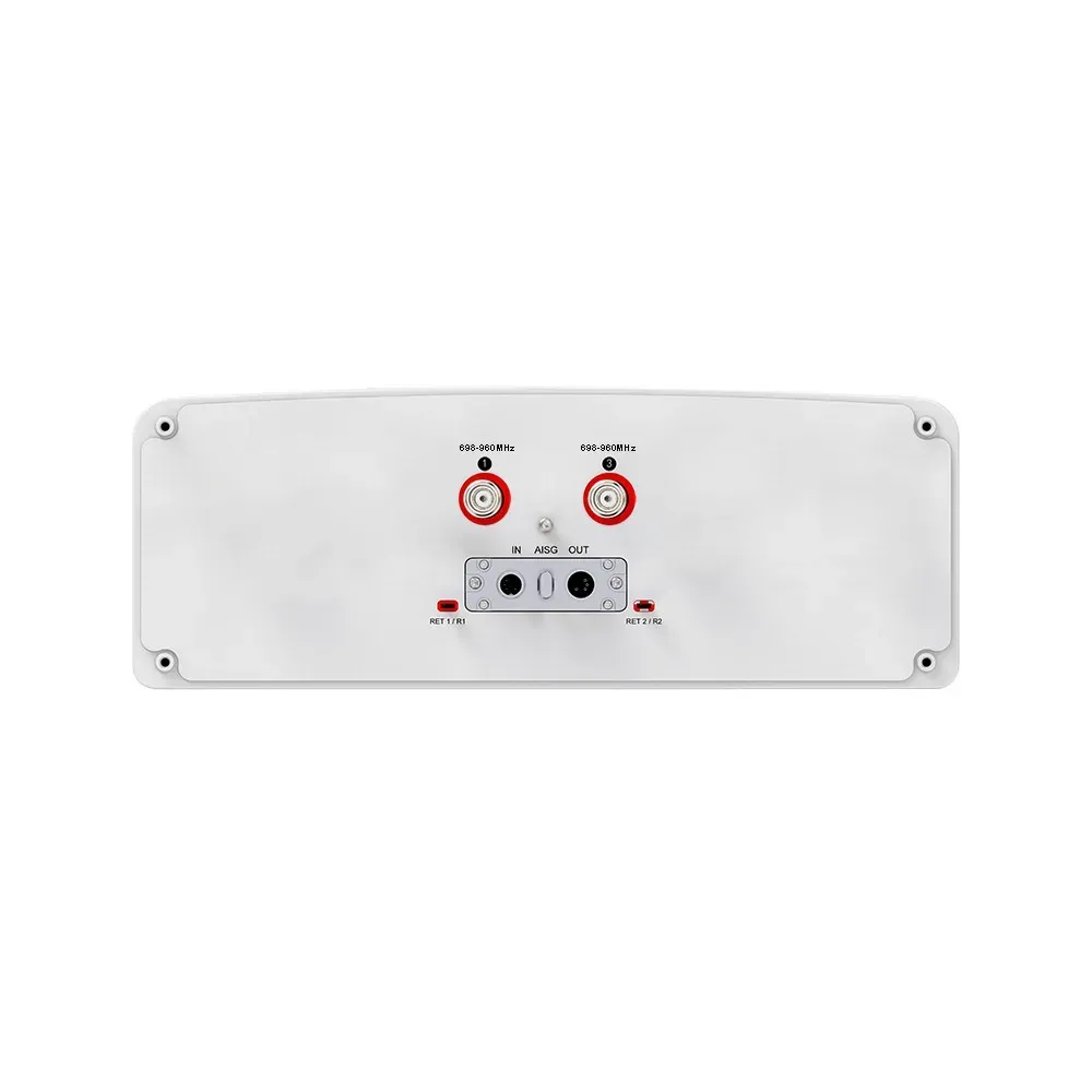
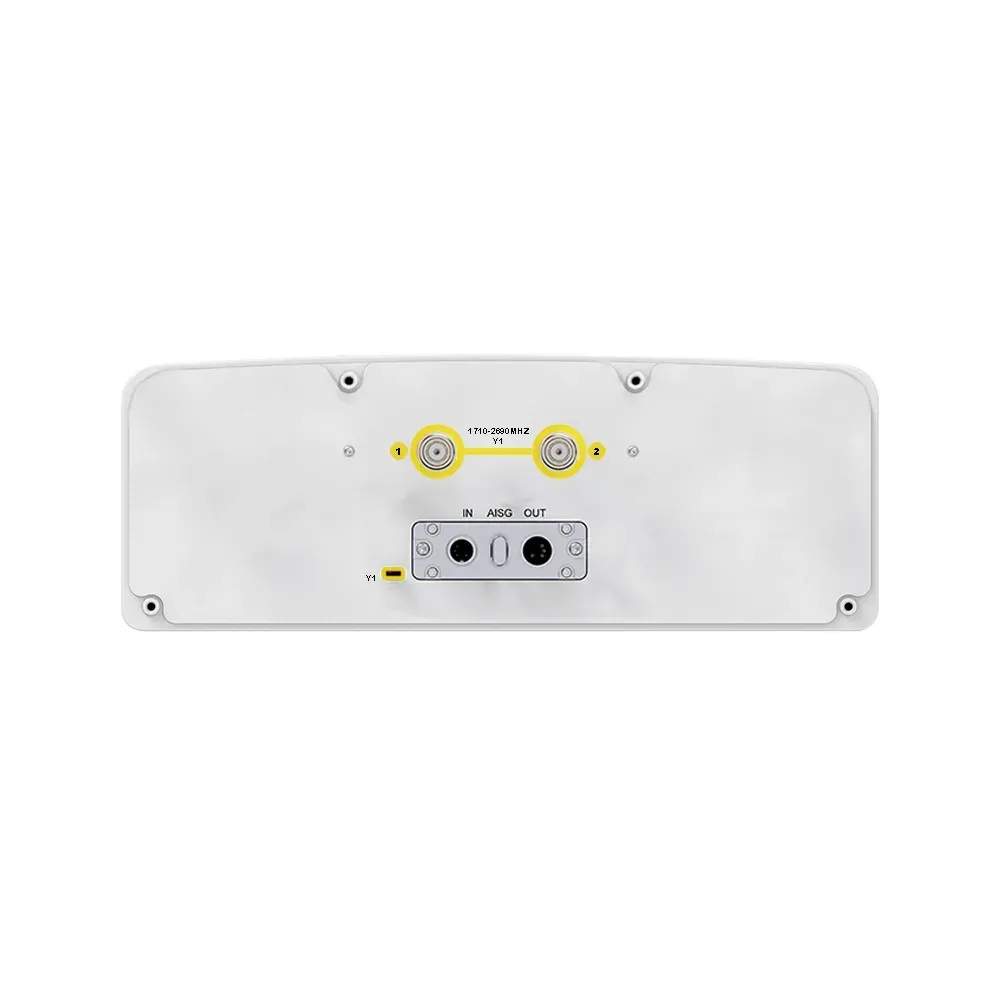
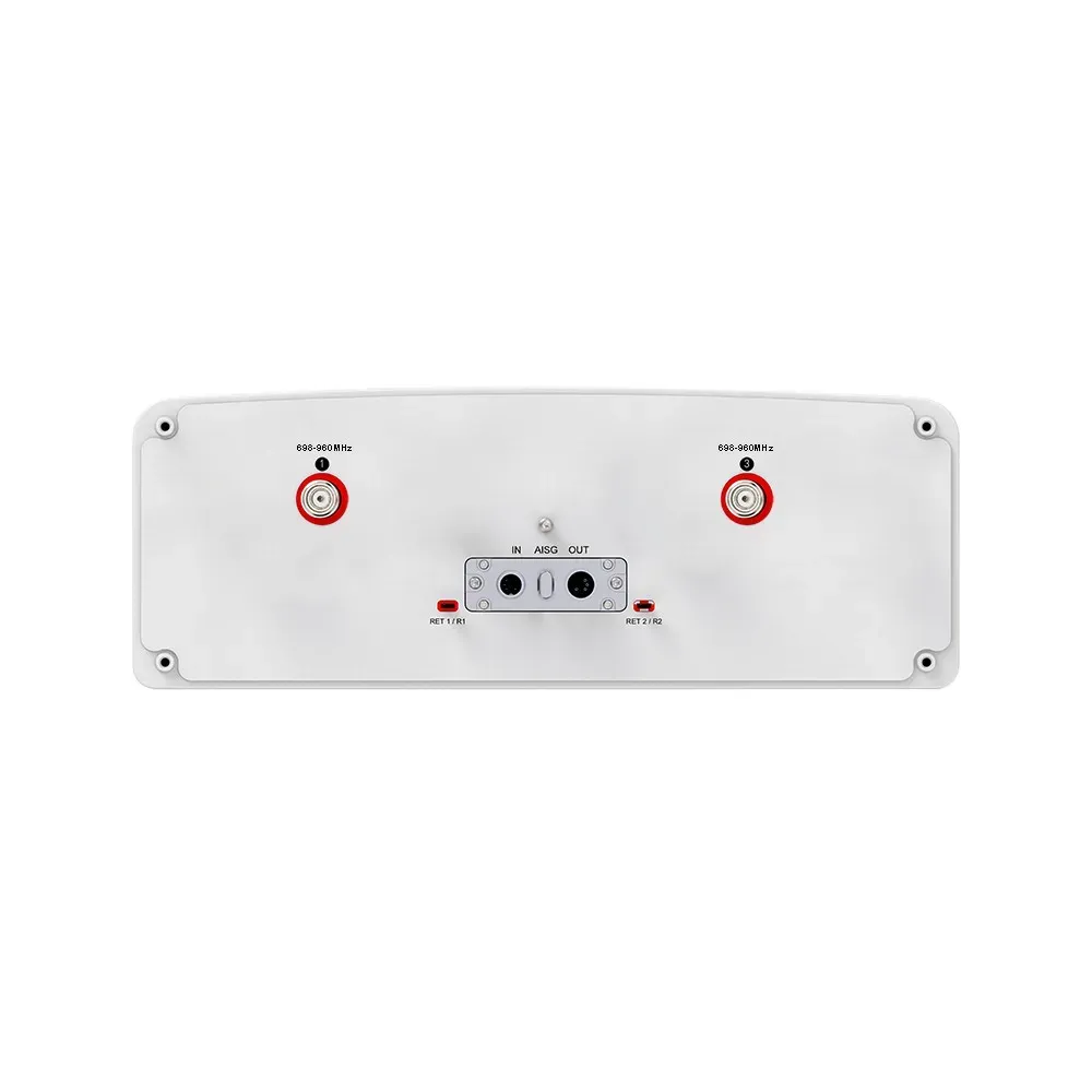
14-Port Antenna | R1 | R2 | R3 | B1 | B2 | Y1 | Y2 |
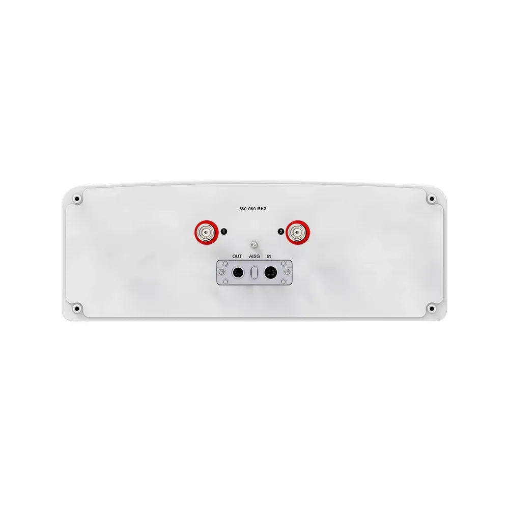
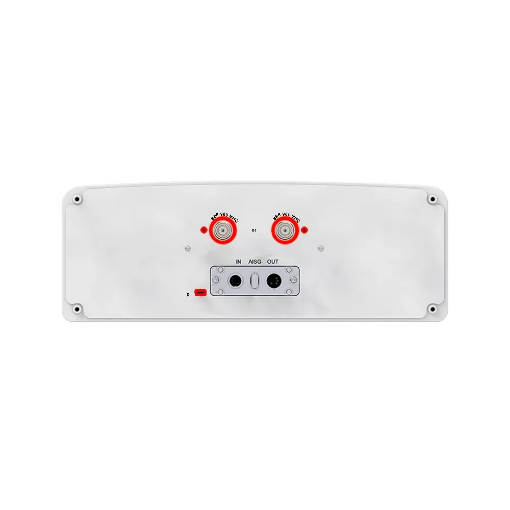
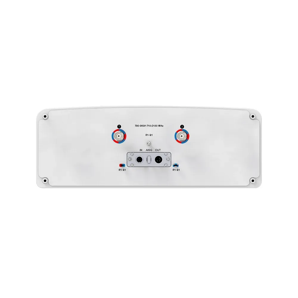
Frequency Range (MHz) | 824-960 | 698-806 | 698-806 | 1710-1880 | 1710-1880 | 2300-2400 | 2300-2400 |
HBW | 65° | 65° | 65° | 65° | 65° | 65° | 65° |
Gain | 14 dBi | 13.5 dBi | 13.5 dBi | 16.5 dBi | 16.5 dBi | 17 dBi | 17 dBi |
Tilt | 2-14° | 2-14° | 2-14° | 0-10° | 0-10° | 0-10° | 0-10° |
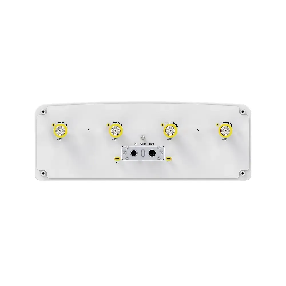
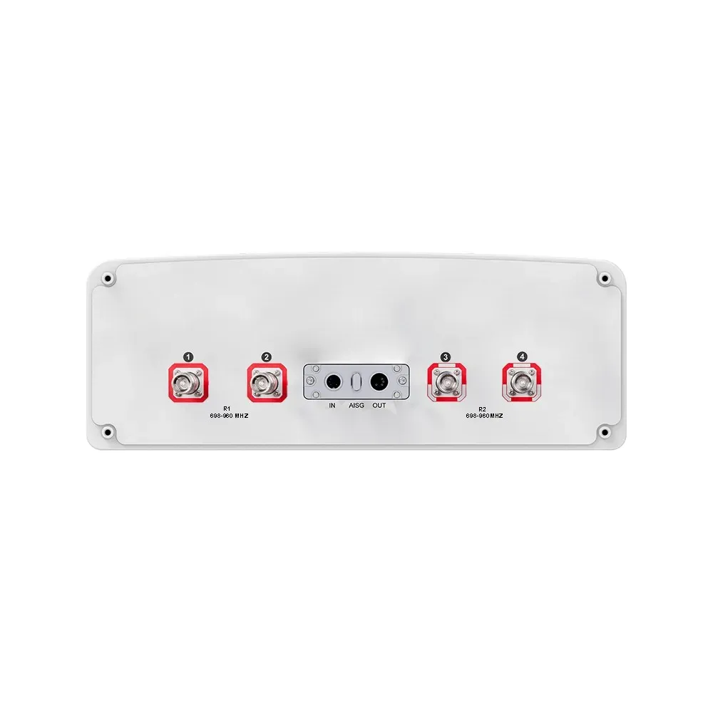
Connectors
(other connectors by request) |
(2x) 7/16-
DIN Female |
(2x) 7/16-
DIN Female |
(2x) 7/16-
DIN Female |
(2x) 7/16-
DIN Female |
(2x) 7/16-
DIN Female |
(2x) 7/16-
DIN Female |
(2x) 7/16-
DIN Female |
Product Part Number
14P-824-2400F-14G-65H15V
Electrical & Mechanical Specification
Electrical Specifications | |||||||
---|---|---|---|---|---|---|---|
R1 | R2 | B1 / B2 | Y1/Y2 | ||||
Frequency Range | MHz | 824-960 | |||||
MHz | 824-894 | 880-960 | 698-806 | 1710-1880 | 2300-2400 | ||
Polarization | — | ±45° | ±45° | ±45° | ±45° | ||
Gain | at Mid Tilt | dBi | 13.8 | 14.1 | 13.5 | 16.4 | 17.2 |
Over All Tilts | dBi | 13.6 ± 0.5 | 13.9 ± 0.5 | 13.3 ± 0.6 | 16.2 ± 0.6 | 17.0 ± 0.6 | |
Horizontal Beamwidth | degree | 67 ± 5.5 | 65 ± 6.5 | 64 ± 6.5 | 64 ± 5.5 | 60 ± 4.5 | |
Vertical Beamwidth | degree | 14.8 ± 0.9 | 14.2 ± 0.9 | 16.7 ± 1.1 | 7.4 ± 0.6 | 6.0 ± 0.5 | |
Electrical Downtilt, Continuously Adjustable | degree | Feb-14 | Feb-14 | 0-10 | 0-10 | ||
First Upper Side Lobe Suppression | dB | > 15 | > 15 | > 15 | > 15 | > 15 | |
Front-To-Back Ratio ±30° | dB | > 25 | > 25 | > 22 | > 25 | > 25 | |
Cross Polar Discrimination at Boresight | dB | > 18 | > 18 | > 18 | > 28 | > 28 | |
Isolation | Cross-Polar | dB | > 25 | > 25 | > 25 | > 25 | |
Port-to-Port | dB | > 25 (R2//R3), | |||||
> 28 | > 28 (R2, R3//R1, B1, B2, Y1, Y2) | > 28 | > 28 | ||||
Impedance | Ohm | 50 | 50 | 50 | 50 | ||
VSWR | — | < 1.5 | < 1.5 | < 1.5 | < 1.5 | ||
Return Loss | dB | > 14 | > 14 | > 14 | > 14 | ||
PIM3 (2×43 dBm Carrier) | dBc | < -150 | < -150 | < -150 | < -150 | ||
Lightning Protection | — | DC Ground | DC Ground | DC Ground | DC Ground | ||
Maximum Average Input Power per Port, at 50° C Ambient Temperature | Watts | 500 | 500 | 600 (B1+Y1/B2+Y2) | |||
Integrated RET Specifications | |||||||
Protocols | Compliant to AISG v2.0 and 3GPP | ||||||
Supply Voltage Range | 10-30 V DC; Compliant to AISG2.0 and 3GPP TS25.461 V6.0.0 | ||||||
Power | Standby | < 2 W | |||||
Consumption | In Motion | < 10 W | |||||
Connectors | 2 x 8 Pin Circle Connector According to IEC 60130-9 and AISG | ||||||
Daisy Chain In: Male; Daisy Chain Out: Female | |||||||
Pin3: RS485B; Pin5: RS485A; Pin6: 10-30 V; Pin7: DC Return | |||||||
Female Connector: 8 PINs; Male Connector: 4 PINs | |||||||
Lightning Protection Rating | IEC 61000-4-5 Current Pulse Profile | ||||||
Line to Ground: 8/20 µs @ 8 kA ≥ ±5 Repititions Line to Line: 8/20 µs @ 3 kA ≥ ±5 Repititions | |||||||
Safety Standard | Compliant to EN 60950/UL 60950/RoHS, CE | ||||||
Mechanical Specifications | |||||||
Connector Type | — | (14x) 7/16-DIN Female | |||||
Connector Position | — | Bottom | |||||
Electrical Tilt Control | — | Integrated RET | |||||
Radome Material | — | Fiberglass | |||||
Antenna Dimensions (H x W x D) | mm (in) | 2497 x 467 x 167 (98.3 x 18.4 x 6.6) | |||||
Antenna Weight | Antenna Only | kg (lbs) | 39 (86.0) | ||||
with Clamps | kg (lbs) | 48 (105.8) | |||||
Maximum Wind Speed | km/h (mph) | 200 (124.3) | |||||
Wind Load At 150 Km/H | Frontal | N (lbf) | 1080 (242.8) | ||||
Rear | N (lbf) | 1205 (270.9) | |||||
Lateral | N (lbf) | 475 (106.8) | |||||
Operating Temperature | °C (°F) | -40 to +60 (-40 to +140) |
Request a Quote
Other Inquiries
Please send purchase request at sales@mtsrl.in