Product code: 19P-698-3700F-17G-65H9V

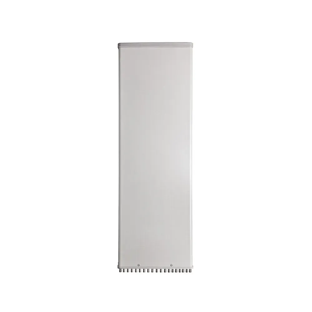
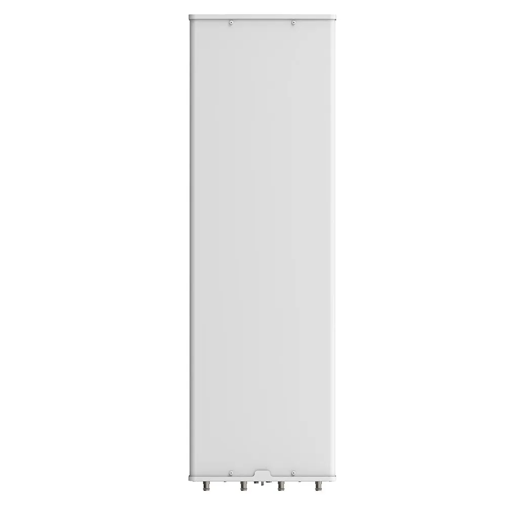
19-Port, TDD Hybrid Panel Antenna, 65° HBW, 698-960/(2x) 1695-2200/(2X) 2300-2690/3300-3700 MHz, 17/17.5/17/17.5/17.5/17 dBi, (5x) 0-10°/(1x) 2-12°T, 2.750 m

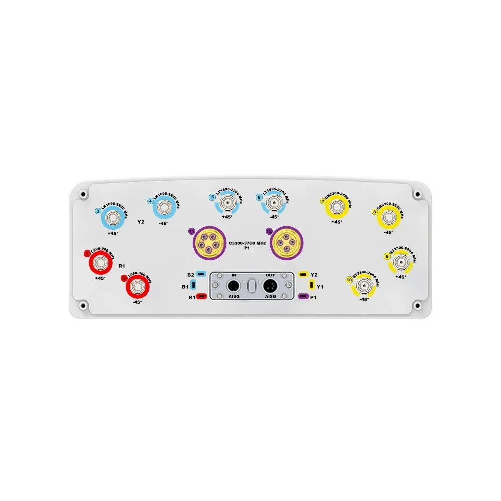
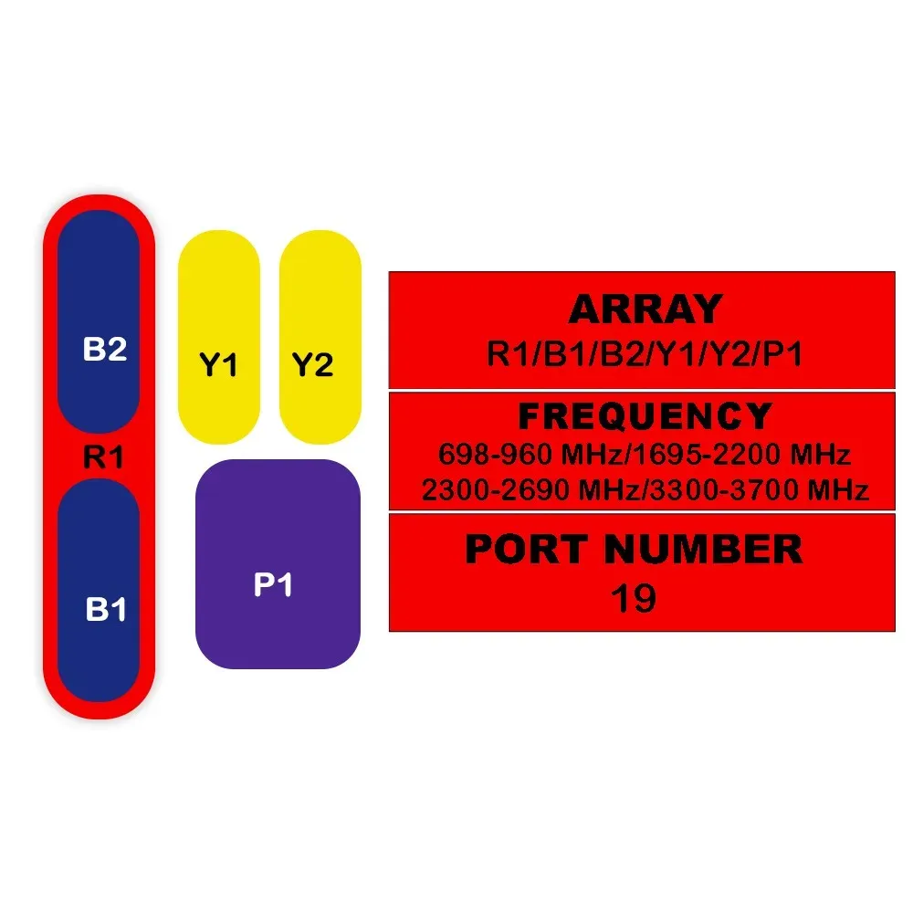
19-Port Antenna R1 B1 B2 Y1 Y2 P1
Frequency Range (MHz) 698-960 1695-2200 1695-2200 2300-2690 2300-2690 3300-3700
HBW 65° 65° 65° 65° 65° 65°
Gain 17 dBi 17.5 dBi 17 dBi 17.5 dBi 17.5 dBi 17 dBi
Tilt 0-10° 0-10° 0-10° 0-10° 0-10° 2-12°
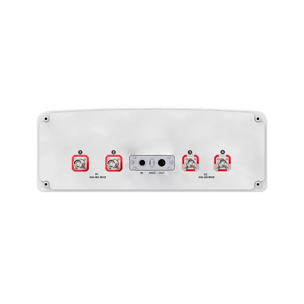
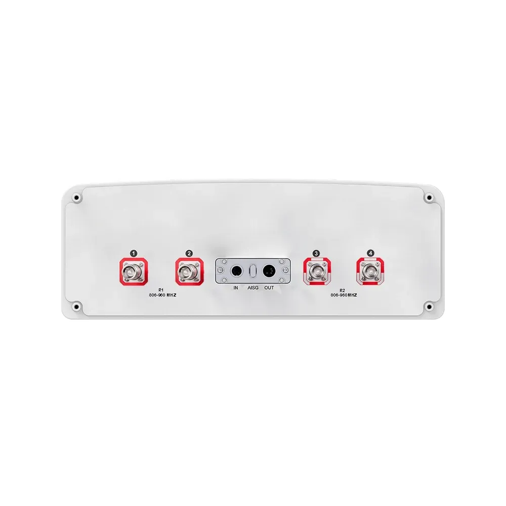
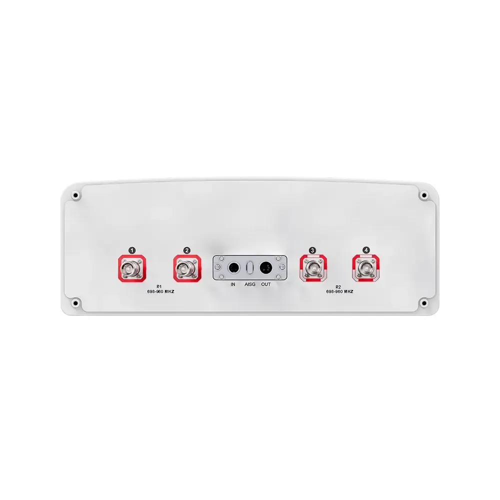
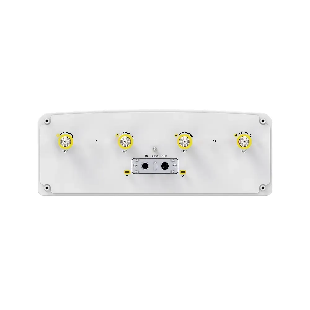
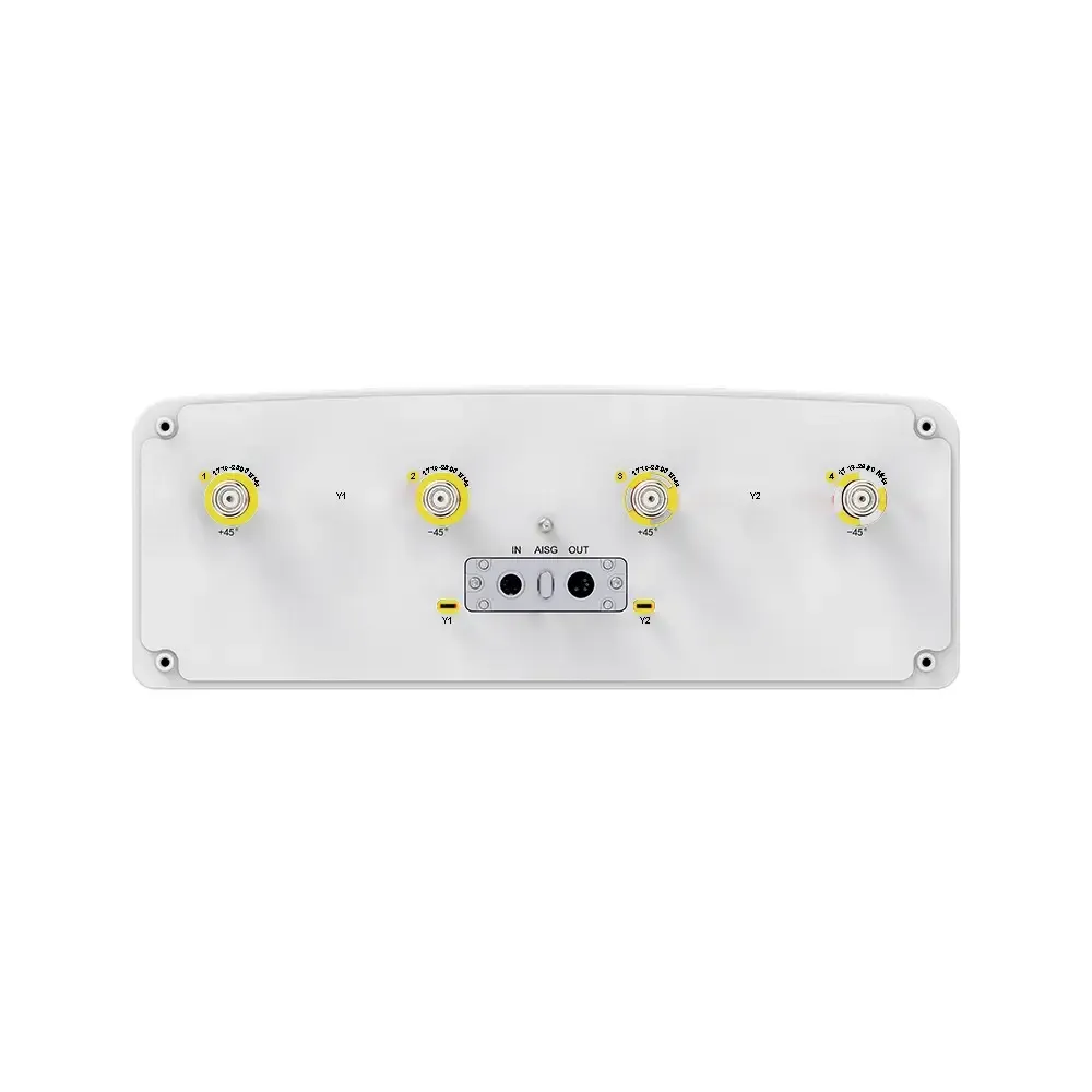
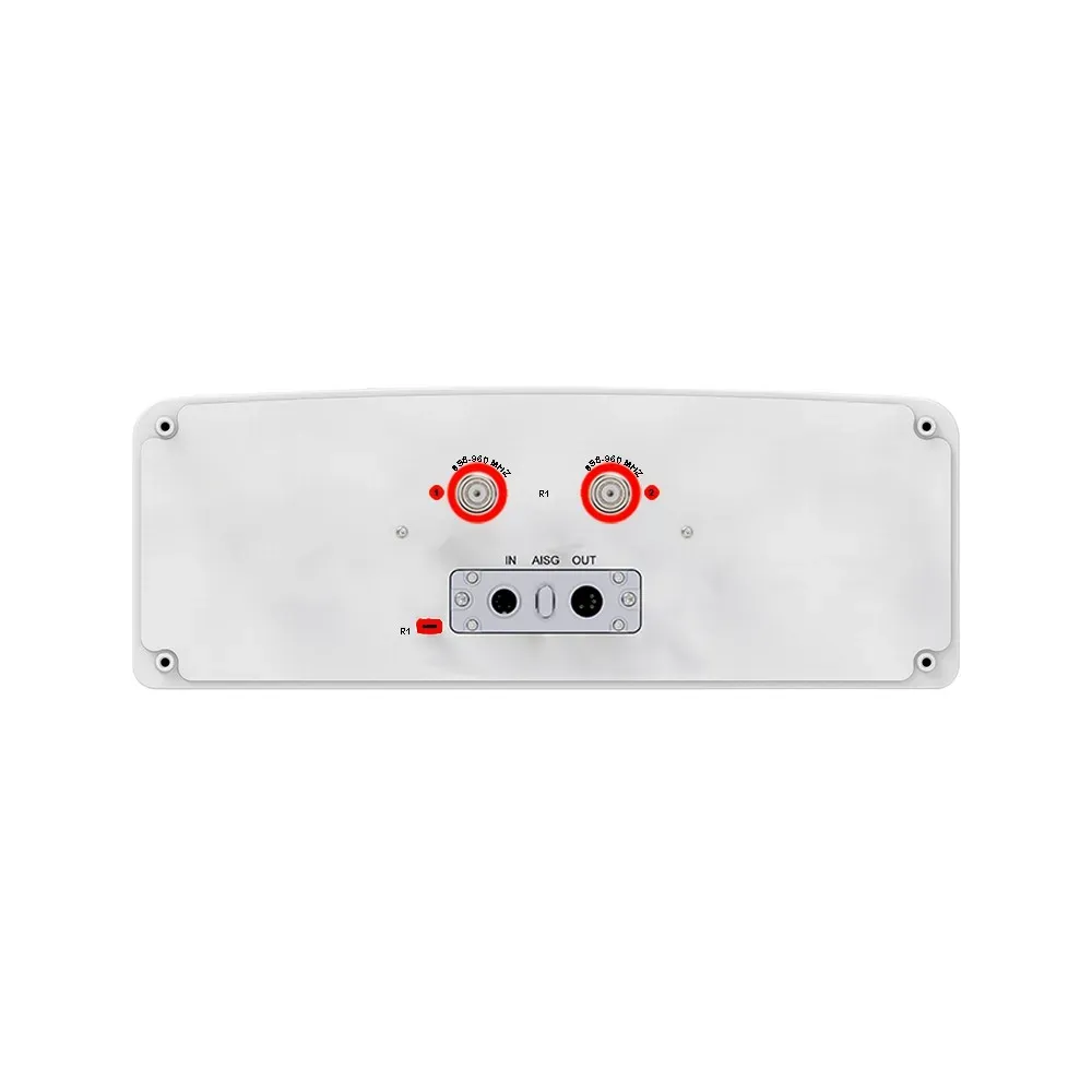
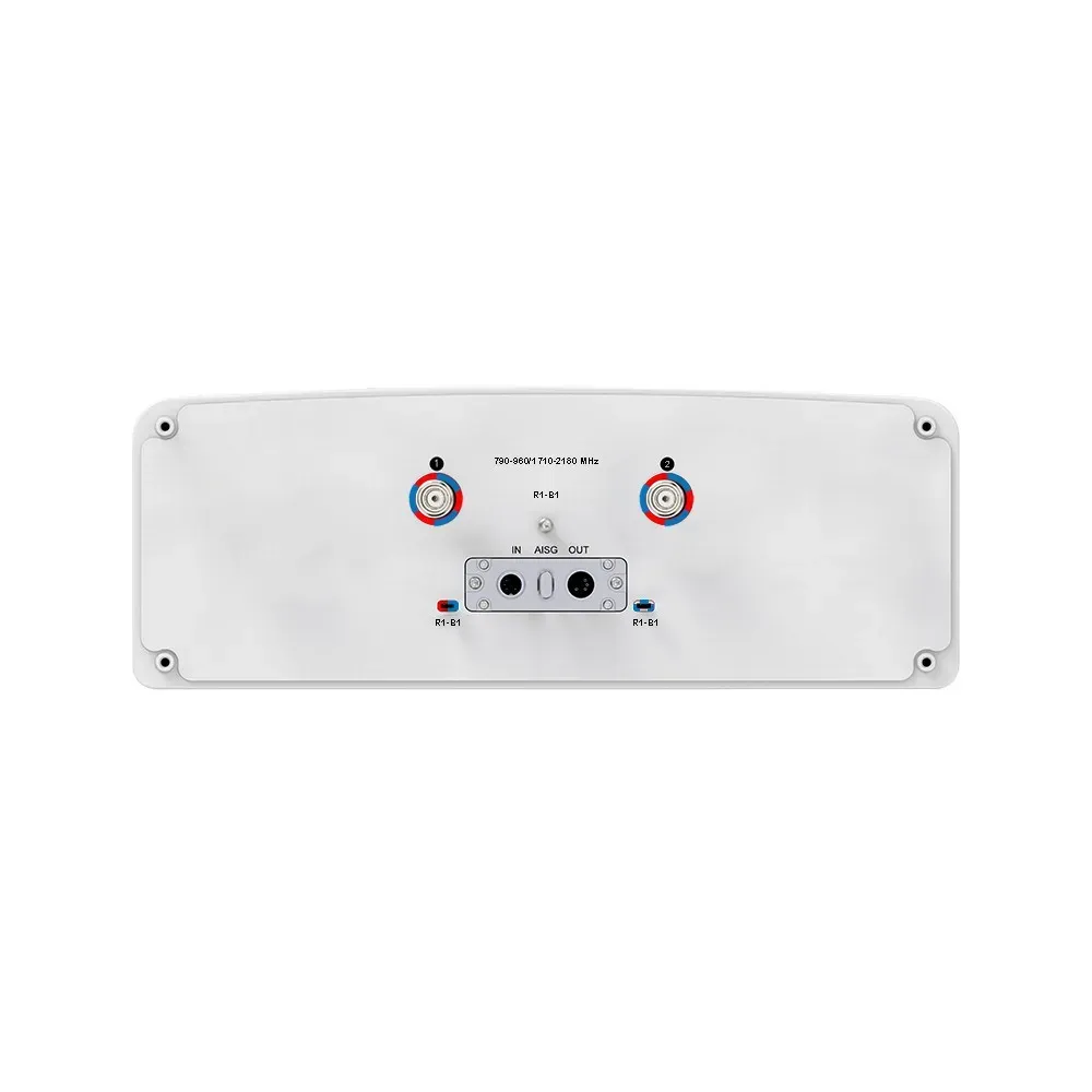
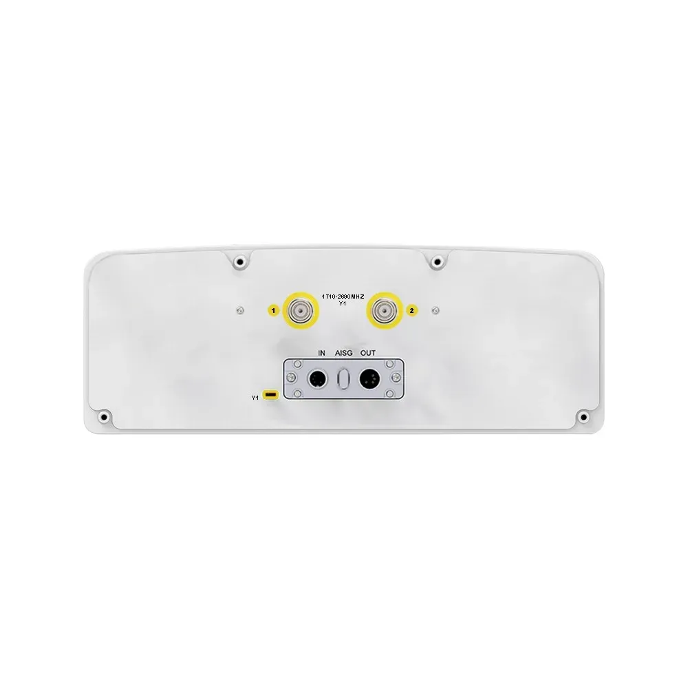
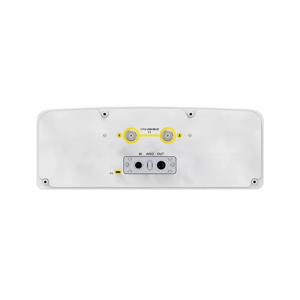
Connectors

(other connectors by request)

(2x) 4.3/10

Female

(2x) 4.3/10

Female

(2x) 4.3/10

Female

(2x) 4.3/10

Female

(2x) 4.3/10

Female

(1x) MQ5 Male + (1x)MQ4 Male


Product Part Number
19P-698-3700F-17G-65H9V
Electrical & Mechanical Specification
Electrical Specifications
R1B1B2
Frequency RangeMHz698-9601695-22001695-2200
MHz698-806790-894880-9601695-18801850-19901920-22001695-18801850-19901920-2200
Polarization±45°±45°±45°
Gainat Mid TiltdBi15.816.216.617.117.417.716.71717.3
Over All TiltsdBi15.6 ± 0.616.0 ± 0.616.4 ± 0.616.9 ± 0.617.2 ± 0.517.5 ± 0.616.5 ± 0.616.8 ± 0.517.1 ± 0.6
Horizontal Beamwidthdegree68 ± 4.566 ± 4.163 ± 4.568 ± 6.566 ± 6.560 ± 5.568 ± 6.566 ± 6.560 ± 5.5
Vertical Beamwidthdegree8.8 ± 1.17.8 ± 0.97.2 ± 0.86.8 ± 0.66.4 ± 0.86.0 ± 0.86.8 ± 0.66.4 ± 0.86.0 ± 0.8
Electrical Downtilt, Continuously Adjustabledegree0-100-100-10
Tilt Accuracydegree< 1< 1< 1< 1< 1< 1< 1< 1< 1
Upper SidelobeFirst Upper LobedB≥ 16≥ 16≥ 16> 15> 15> 15> 15> 15> 15
Suppression20° Sector Above Main BeamdB> 15> 15> 15> 15> 15> 15> 15> 15> 15
Front-To-Back Ratio ±30°dB≥ 22≥ 23≥ 24> 24> 24> 25> 24> 24> 25
Cross Polarat BoresightdB≥ 17≥ 18≥ 17> 18> 18> 18> 18> 18> 18
DiscriminationOver SectordB≥ 8≥ 7≥ 6> 6.0> 7.0> 7.0> 6.0> 7.0> 7.0
IsolationCross-PolardB> 26> 28> 28
Port-to-PortdB> 28> 28> 28
ImpedanceOhm505050
VSWR< 1.5< 1.5< 1.5
Return LossdB> 14> 14> 14
PIM3 (2×43 dBm Carrier)dBc< -150< -150< -150
Lightning ProtectionDC GroundDC GroundDC Ground
Maximum Average Input Power per Port, at 50° C Ambient TemperatureWatts250200200
Y1 / Y2TDD LTE Specifications ContinuedP1TDD LTE SpecificationsP1
Frequency RangeMHz2300-2690Service0° Direct Beam GainGaindBi21.5Frequency RangeMHz3300-3700
MHz2300-24002490-2690BeamHorizontal Beamwidth (3 dB)degree26Polarization±45°
Polarization±45°Cross Polar Ratio (Beam-Peak)dB≥ 16Electrical Downtiltdegree2-12
Gainat Mid TiltdBi17.517.5Front-To-Back Ratio ±30°dB≥ 27Single Column BeamGaindBi17
Over All TiltsdBi17.3 ± 0.717.3 ± 0.7Horizontal SidelobedB12Horizontal Beamwidthdegree75
Horizontal Beamwidthdegree58 ± 6.558 ± 6.5±30° DirectGaindBi20Vertical Beamwidth (3 dB)degree5.8
Vertical Beamwidthdegree5.4 ± 0.44.8 ± 0.6Beam GainHorizontal Beamwidth (3 dB)degree28Cross-Polar Ratio (at Boresight)dB≥ 15
Electrical Downtilt, Continuously Adjustabledegree0-10Front-To-Back RatiodB≥ 24Cross-Polar Ratio (Over Sector)dB≥ 8
Tilt Accuracydegree< 1< 1Soft Split Multi-BeamGaindBi20First Upper Sidelobe SuppressiondB≥ 15
Upper SidelobeFirst Upper SidelobedB> 15> 15Horizontal Beamwidth (3 dB)degree31Front-To-Back RatiodB≥ 23
Suppression20° Sector Above Main BeamdB> 14> 14Front-To-BackdB≥ 2565°GaindB18
Front-To-Back Ratio ±30°dB> 24> 24Calibration and Electrical ParameterCoupling Factor Between CalibrationdB-26 ± 2Broadcast BeamHorizontal Beamwidth (3 dB)degree65
Cross Polarat BoresightdB> 17> 17And Each Antenna PortVertical Beamwidth (3 dB)degree5.8
DiscriminationOver SectordB> 4.0> 3.0Max. Amplitude Tolerance From Calibration Port To Input PortsdB≤ 1.0Cross-Polar Ratio (0°)dB≥ 15
IsolationCross-PolardB> 28Max. Phase Tolerance From Calibration Port To Input PortsdB≤ 9First Upper Sidelobe SuppressiondB≥ 15
Port-to-PortdB> 28VSWR<1.5Front-To-Back Ratio ±30°dB≥ 25
ImpedanceOhm50Average Power CapacityW25
VSWR< 1.5IsolationIntrbanddB≥ 23
Return LossdB> 14InterbanddB≥ 23
PIM3 (2×43 dBm Carrier)dBc< -150ImpedanceOhm50
Lightning ProtectionDC GroundLightning ProtectionDC Ground
Maximum Average Input Power per Port, at 50° C Ambient TemperatureWatts200
5G NR Specifications
Frequency RangeMHz3300-3700
Single Column BeamGaindBi17
Horizontal Beamwidth (3 dB)degree75
Vertical Beamwidth (3 dB)degree5.8
Cross-Polar Discrimination (at Boresight)dB≥ 15
Cross-Polar Discrimination (Over Sector)dB≥ 8
First Upper Side Lobe SuppressiondB≥ 15
NRGaindBi21
Broadcast Beam (±13°,Horizontal Beamwidth (10 dB)degree120
±43° Four Narrow Beam)Vertical Beamwidth (3 dB)degree5.8
First Upper Side Lobe SuppressiondB≥ 15
Front-To-Back RatiodB≥ 25
NR Service0° Direct Beam GainGaindBi21.5
BeamHorizontal Beamwidth (3 dB)degree26
Cross Polar Ratio (Beam-peak)dB≥ 16
Front-To-Back RatiodB≥ 27
Horizontal SidelobedB12
Integrated RET Specifications
ProtocolsCompliant to AISG v2.0 and 3GPP
Supply Voltage Range10-30 V DC; Compliant to AISG2.0 and 3GPP TS25.461 V6.0.0
PowerStandby< 2 W
ConsumptionIn Motion< 10 W
Connectors2 x 8 Pin Circle Connector According to IEC 60130-9 and AISG Daisy Chain In: Male; Daisy Chain Out: Female
Pin3: RS485B; Pin5: RS485A; Pin6: 10-30 V; Pin7: DC Return
Female Connector: 8 PINs; Male Connector: 4 PINs
Lightning Protection RatingIEC 61000-4-5 Current Pulse Profile
Line to Ground: 8/20 µs @ 8 kA ≥ ±5 Repititions Line to Line: 8/20 µs @ 3 kA ≥ ±5 Repititions
Safety StandardCompliant to EN 60950/UL 60950/RoHS, CE
Mechanical Specification
Connector Type(10x) 4.3/10 Female + (1x) MQ5 Male + (1x) MQ4 Male
Connector PositionBottom
Radome MaterialFiberglass
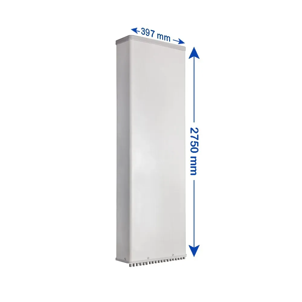
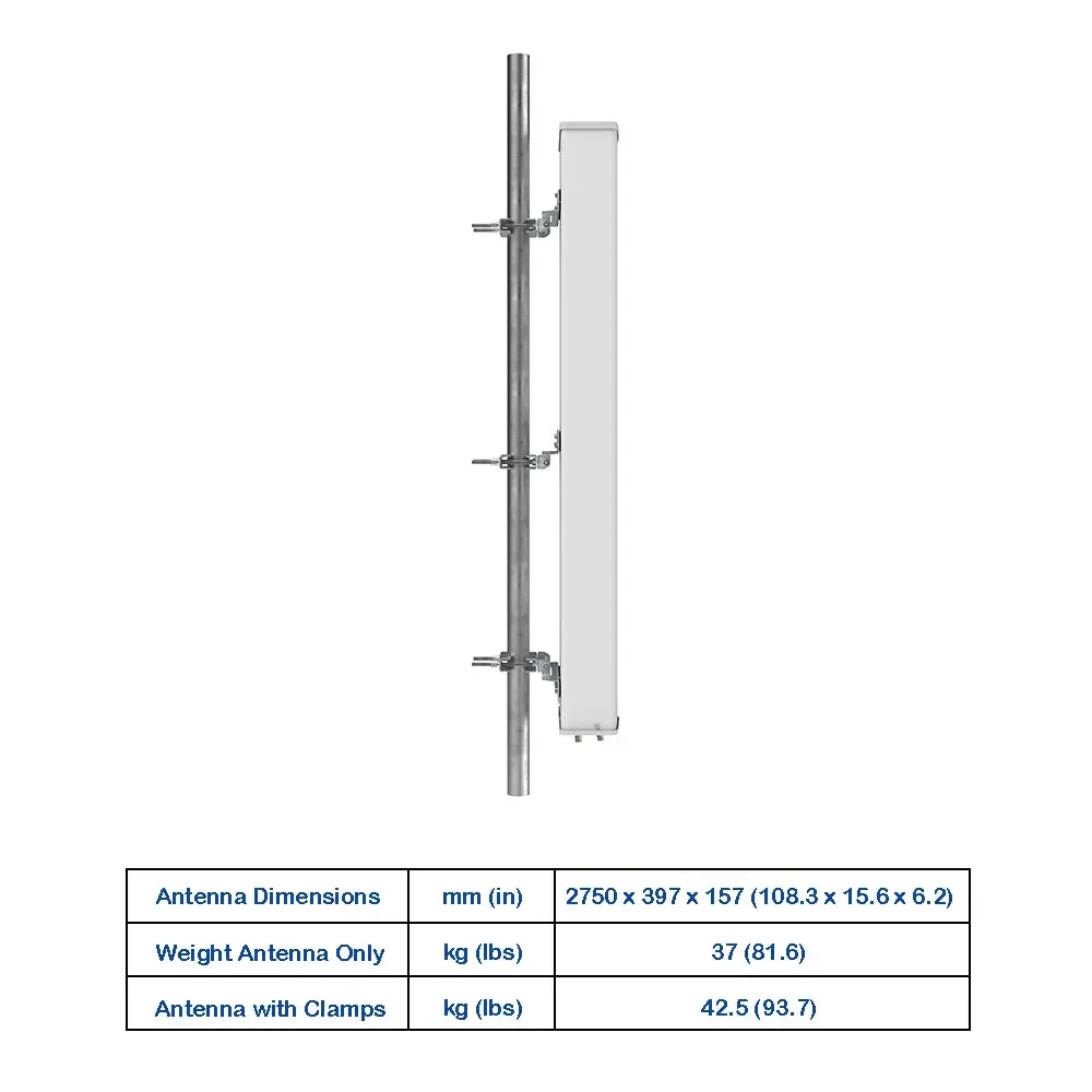
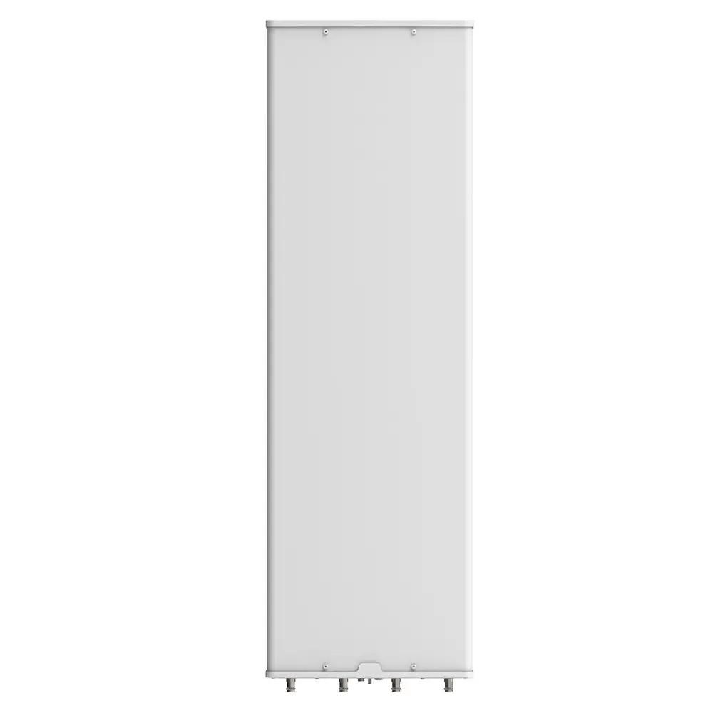
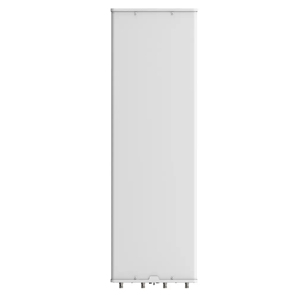
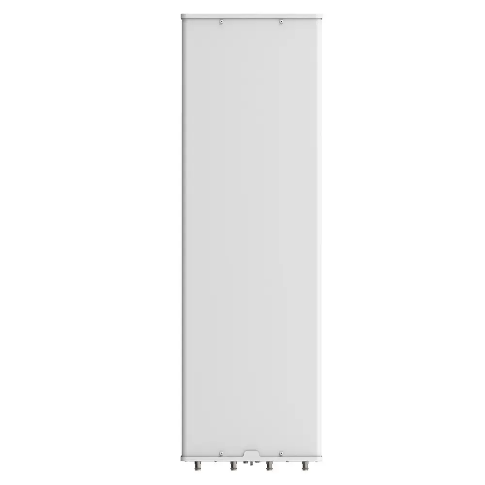
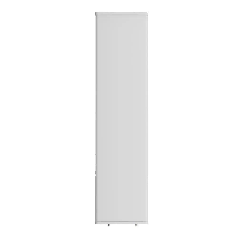
Antenna Dimensions (H x W x D)mm (in)2750 x 397 x 157 (108.3 x 15.6 x 6.2)
Antenna WeightAntenna Onlykg (lbs)37 (81.6)
with Clampskg (lbs)42.5 (93.7)
Maximum Wind Speedkm/h (mph)200 (124.3)
Wind LoadFrontalN (lbf)1005 (225.9)
at 150 km/hRearN (lbf)1125 (252.9)
LateralN (lbf)490 (110.2)
Operating Temperature°C (°F)-40 to +60 (-40 to +140)
Request a Quote
Other Inquiries

Please send purchase request at sales@mtsrl.in