


| 25-Port Antenna |
R1 |
R2 | B1 | B2 | Y1 | Y2 | Y3 | Y4 |
P1 |
| Frequency Range (MHz) |
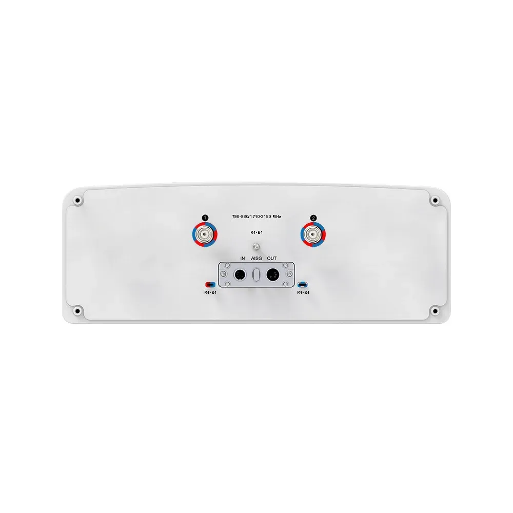
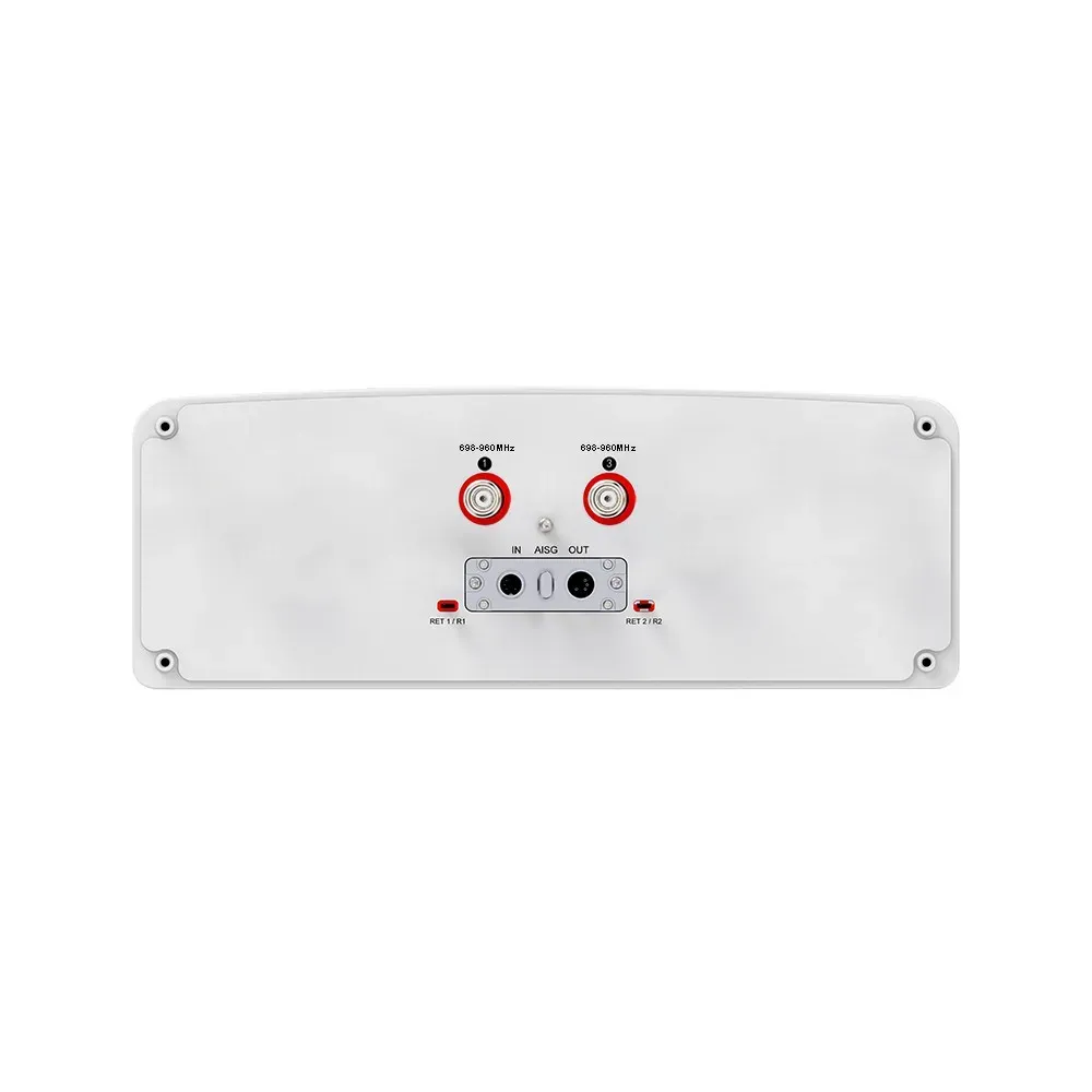
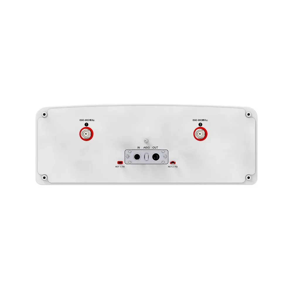
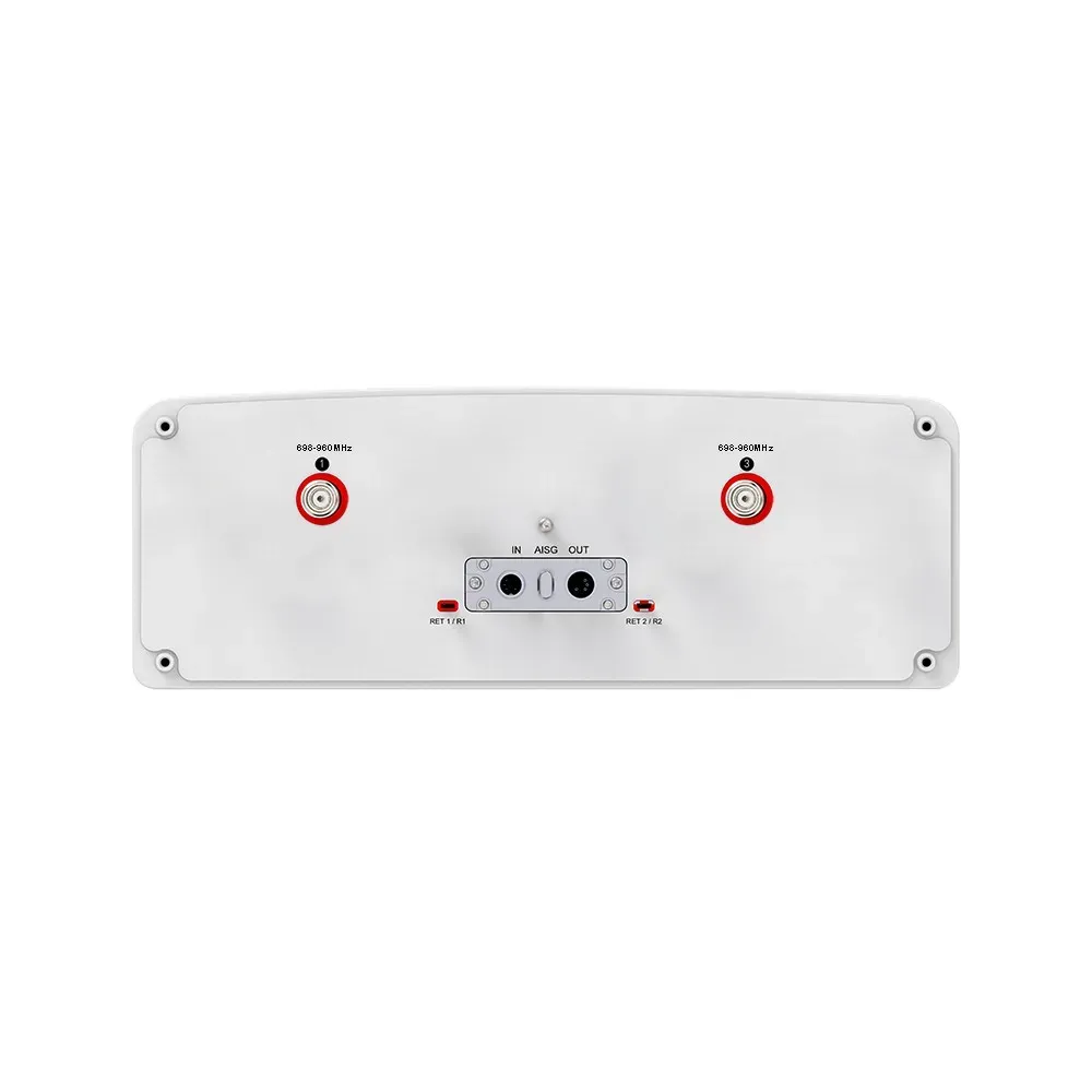
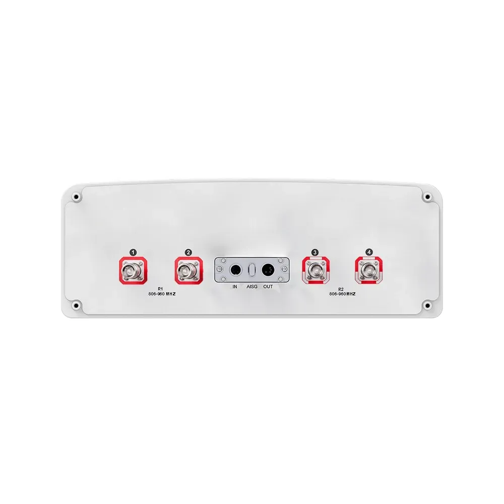
690-960 |
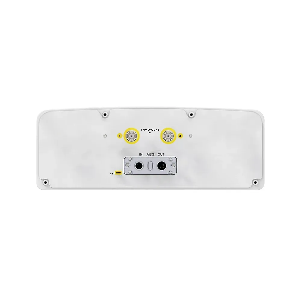
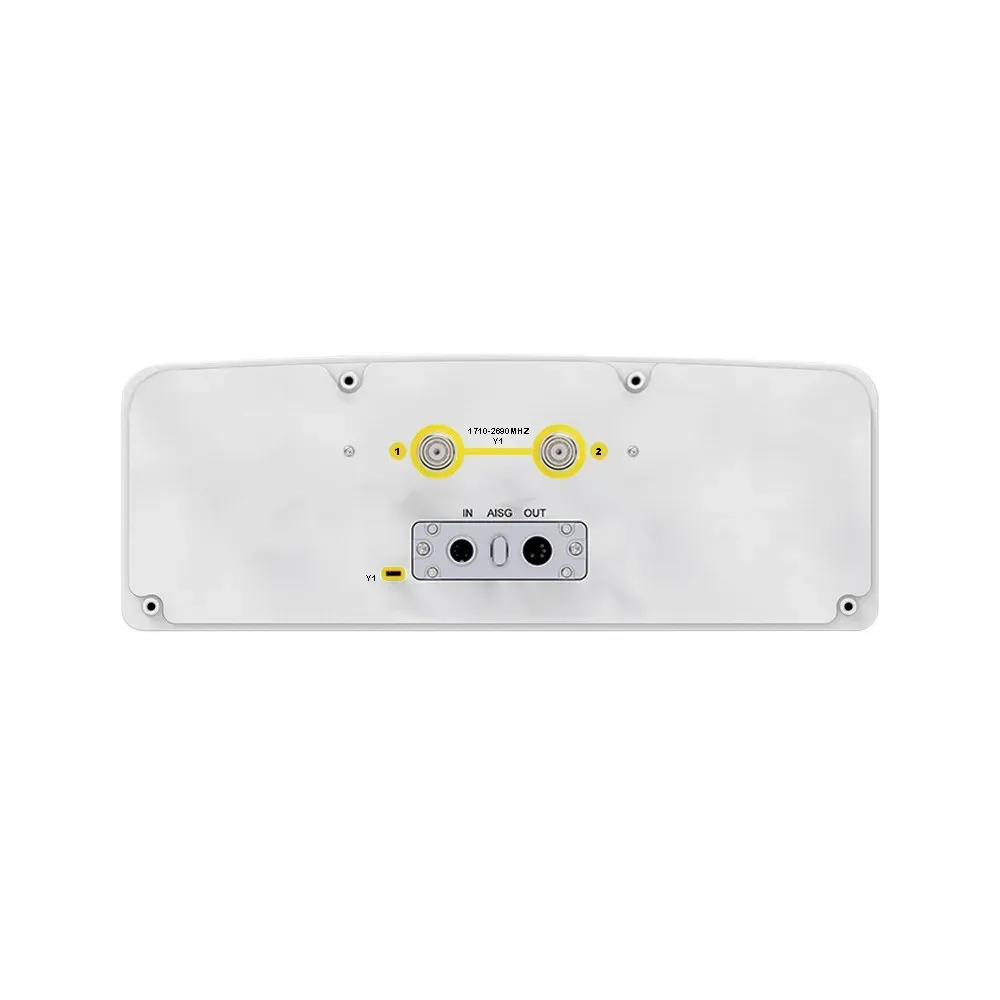
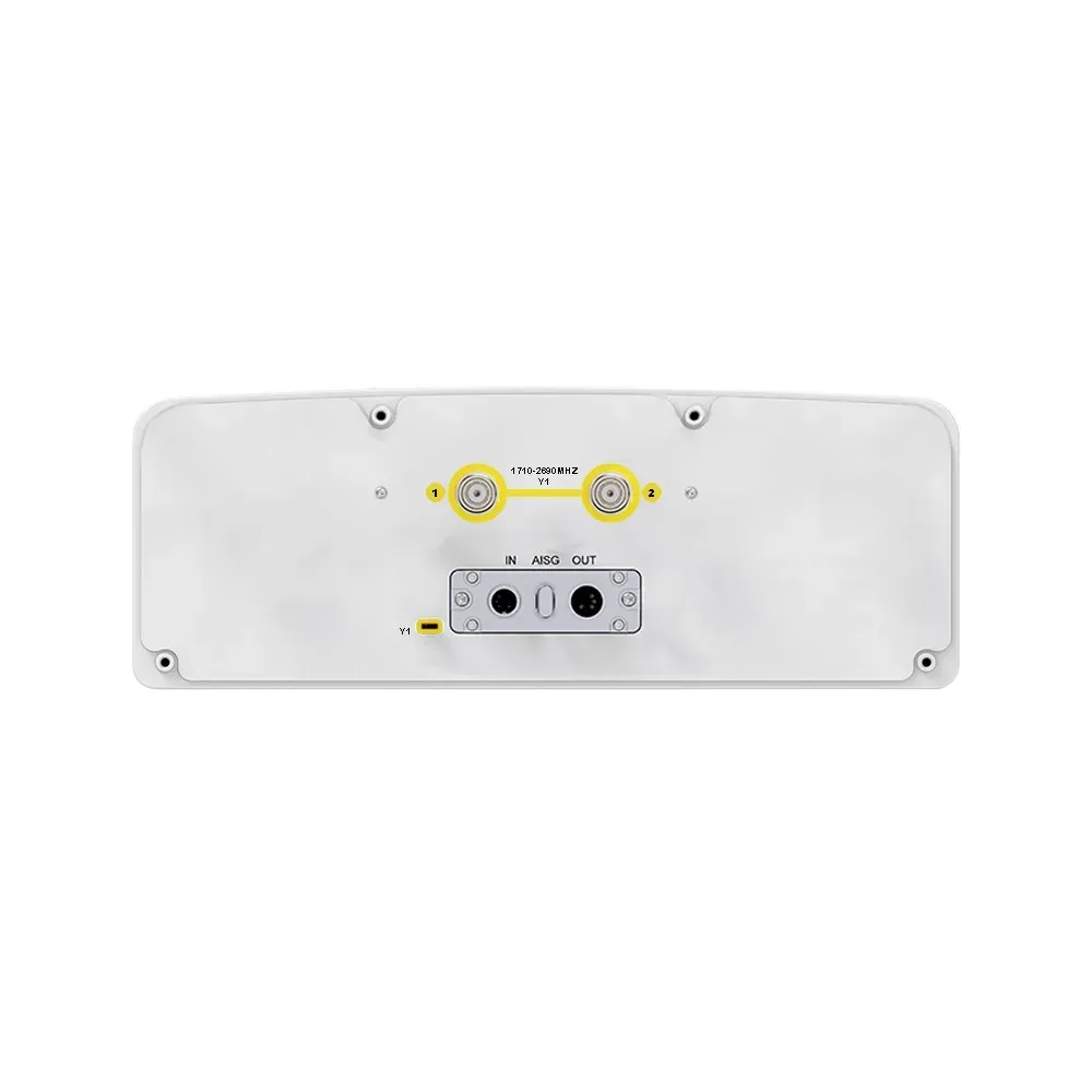
690-960 | 1695-2200 | 1695-2200 | 2490-2690 | 1427-2690 | 1427-2690 | 2490-2690 |
2300-3800 |
| HBW |
65° |
65° | 65° | 65° | 65° | 65° | 65° | 65° |
65° |
| Gain |
16 dBi |
16 dBi | 17 dBi | 17 dBi | 17 dBi | 17 dBi | 17 dBi | 17 dBi |
17 dBi |
| Tilt |
2-12° |
2-12° | 2-12° | 2-12° | 2-12° | 2-12° | 2-12° | 2-12° |
2-12° |
| Connectors
(other connectors by request) |
(2x) 4.3/10 Female |
(2x) 4.3/10
Female |
(2x) 4.3/10
Female |
(2x) 4.3/10
Female |
(2x) 4.3/10
Female |
(2x) 4.3/10
Female |
(2x) 4.3/10
Female |
(2x) 4.3/10
Female |
(1x)MQ5
Male+ (1x) MQ4 Male |