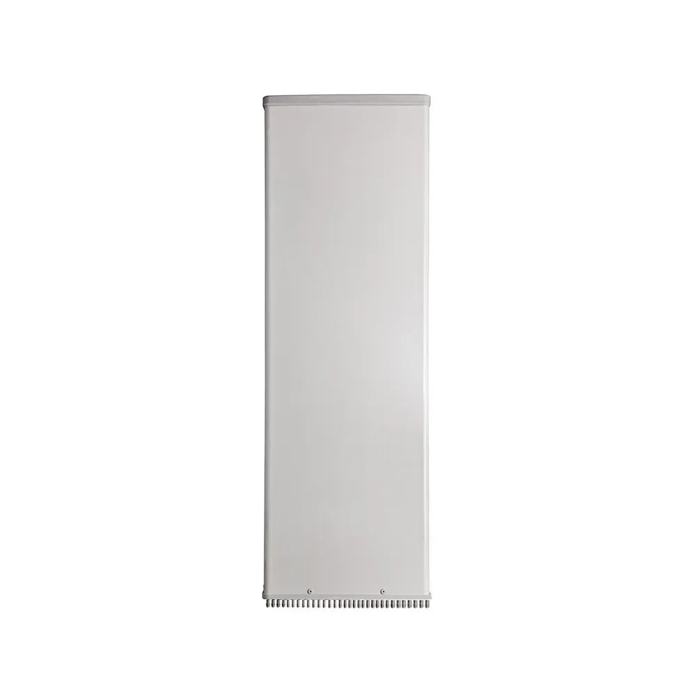
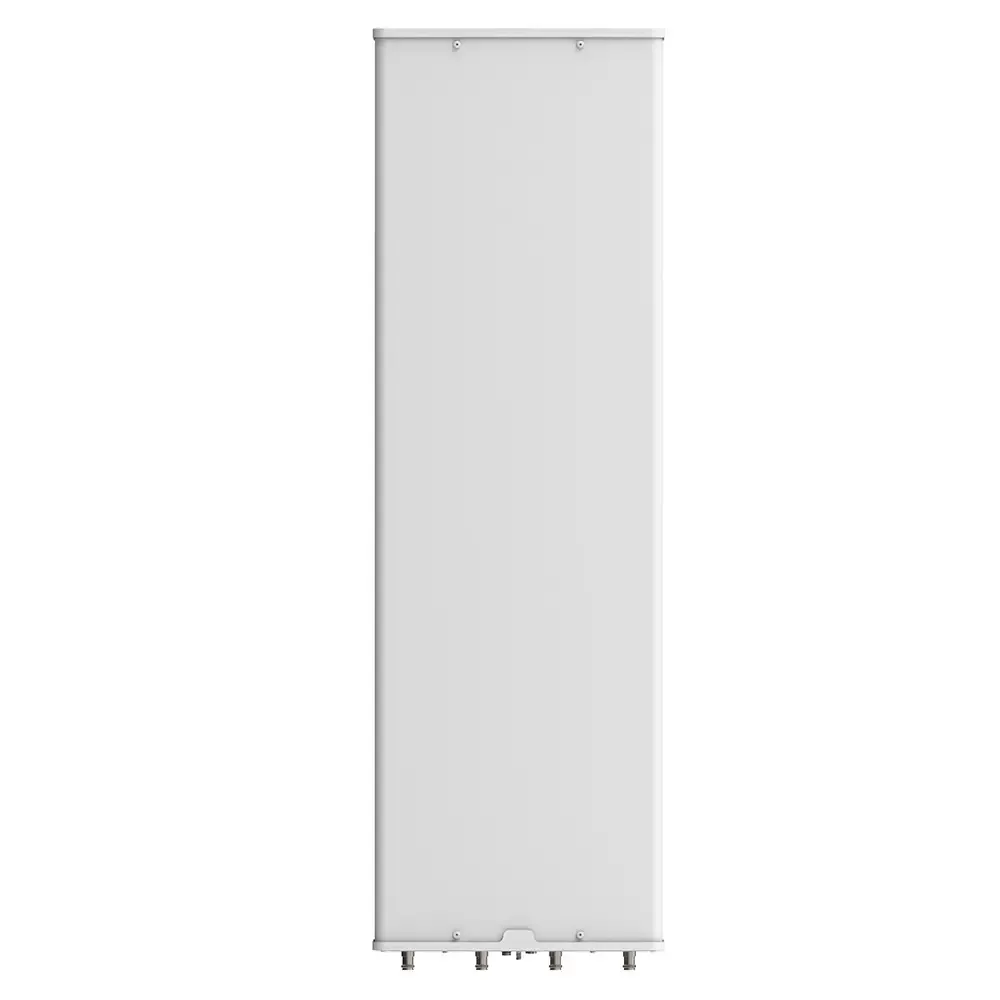
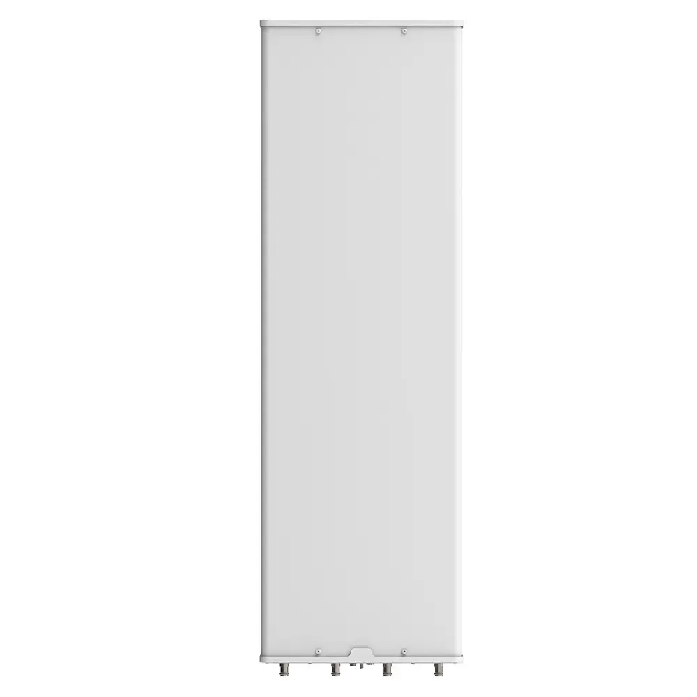
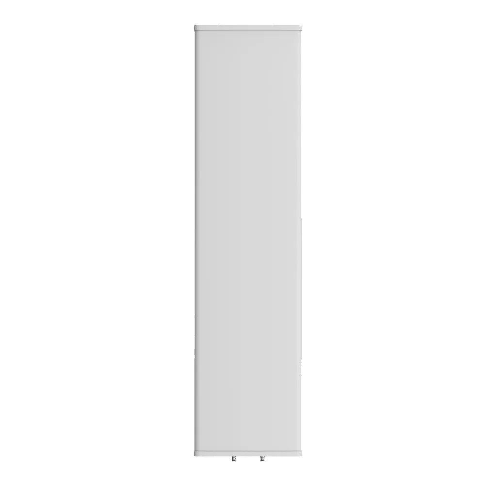
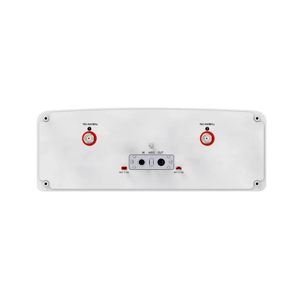
Product code: 32P-694-3800F-16G-65H9V

32-Port, TDD Hybrid Panel Antenna, 65° HBW, 694-862 / 880-960 / 694-960 / (2x) 1427-2690 / (2x) 1695-2690 / 2300-2690 / 3300-3800 MHz, 15.5/16/16.5/18/17.5/18/17.5/17.5/17 dBi, 2-12°T, 2.750 m

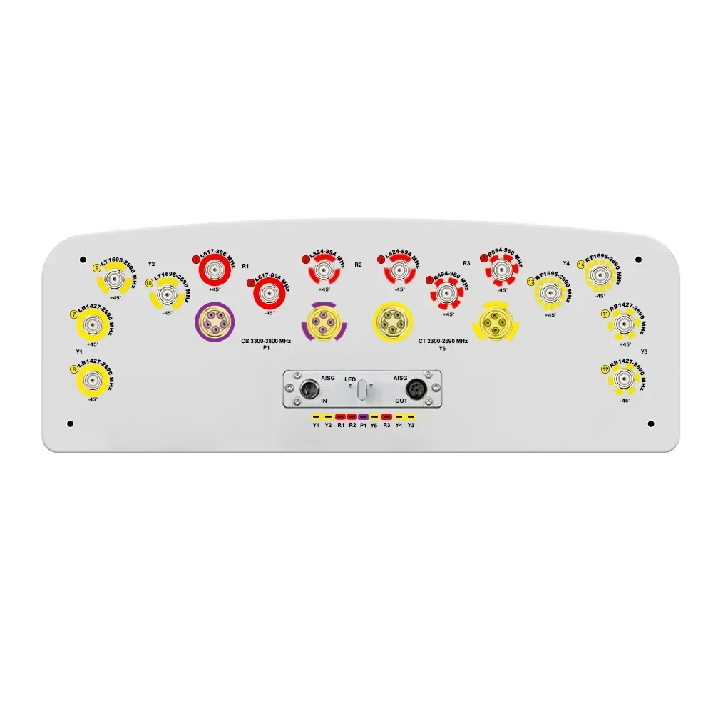
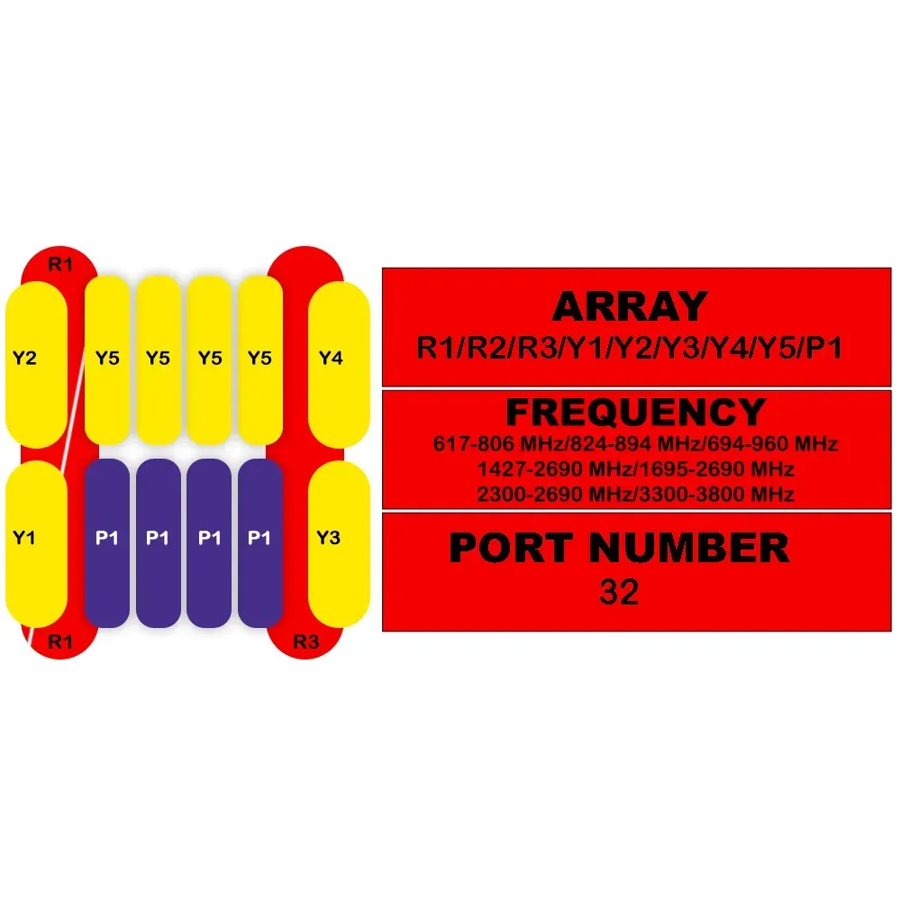
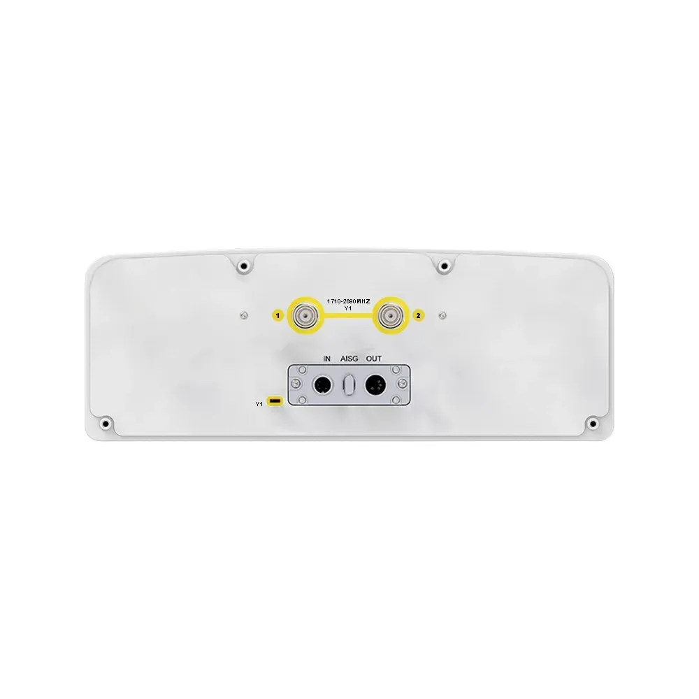
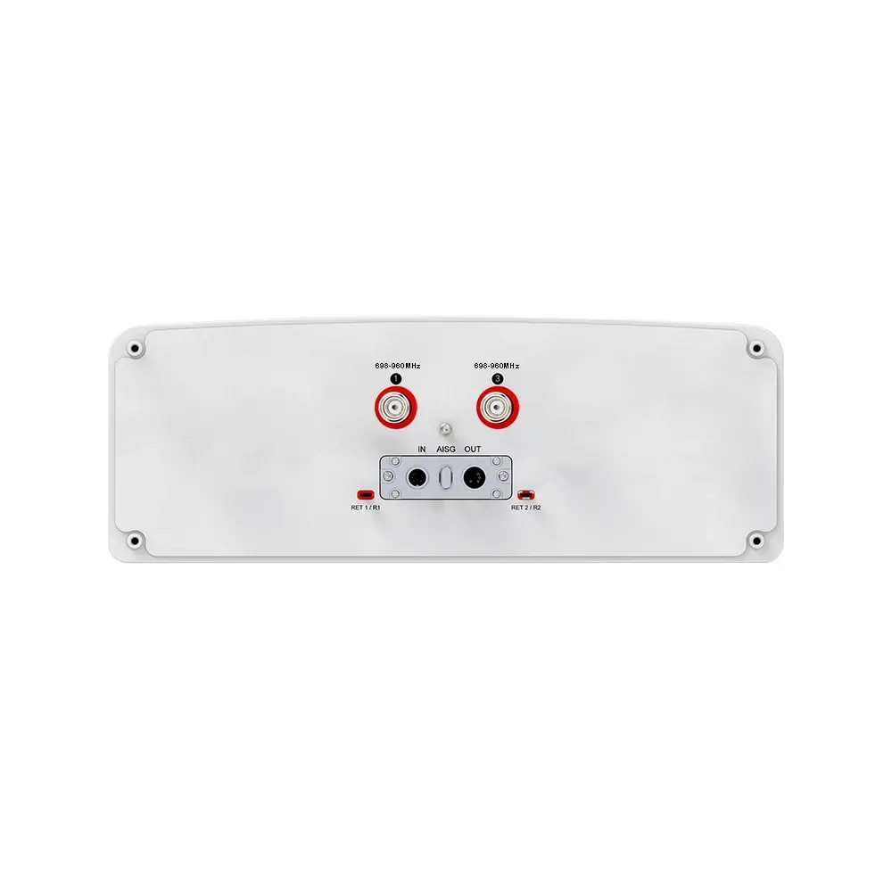
32-Port Antenna R1 R2 R3 Y1 Y2 Y3 Y4 Y5 P1
Frequency Range (MHz) 694-862 880-960 694-960 1427-2690 1695-2690 1427-2690 1695-2690 2300-2690 3300-3800
HBW 65° 65° 65° 65° 65° 65° 65° 65° 65°
Gain 15.5 dBi 16 dBi 16.5 dBi 18 dBi 17.5 dBi 18 dBi 17.5 dBi 17.5 dBi 17 dBi
Tilt 2-12° 2-12° 2-12° 2-12° 2-12° 2-12° 2-12° 2-12° 2-12°
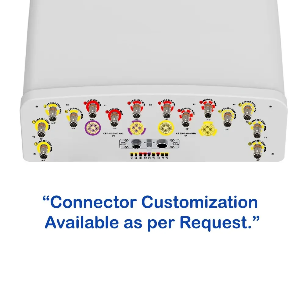
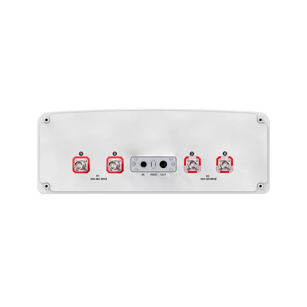
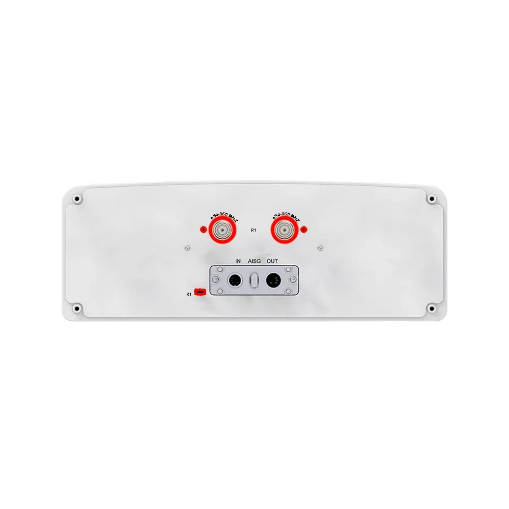
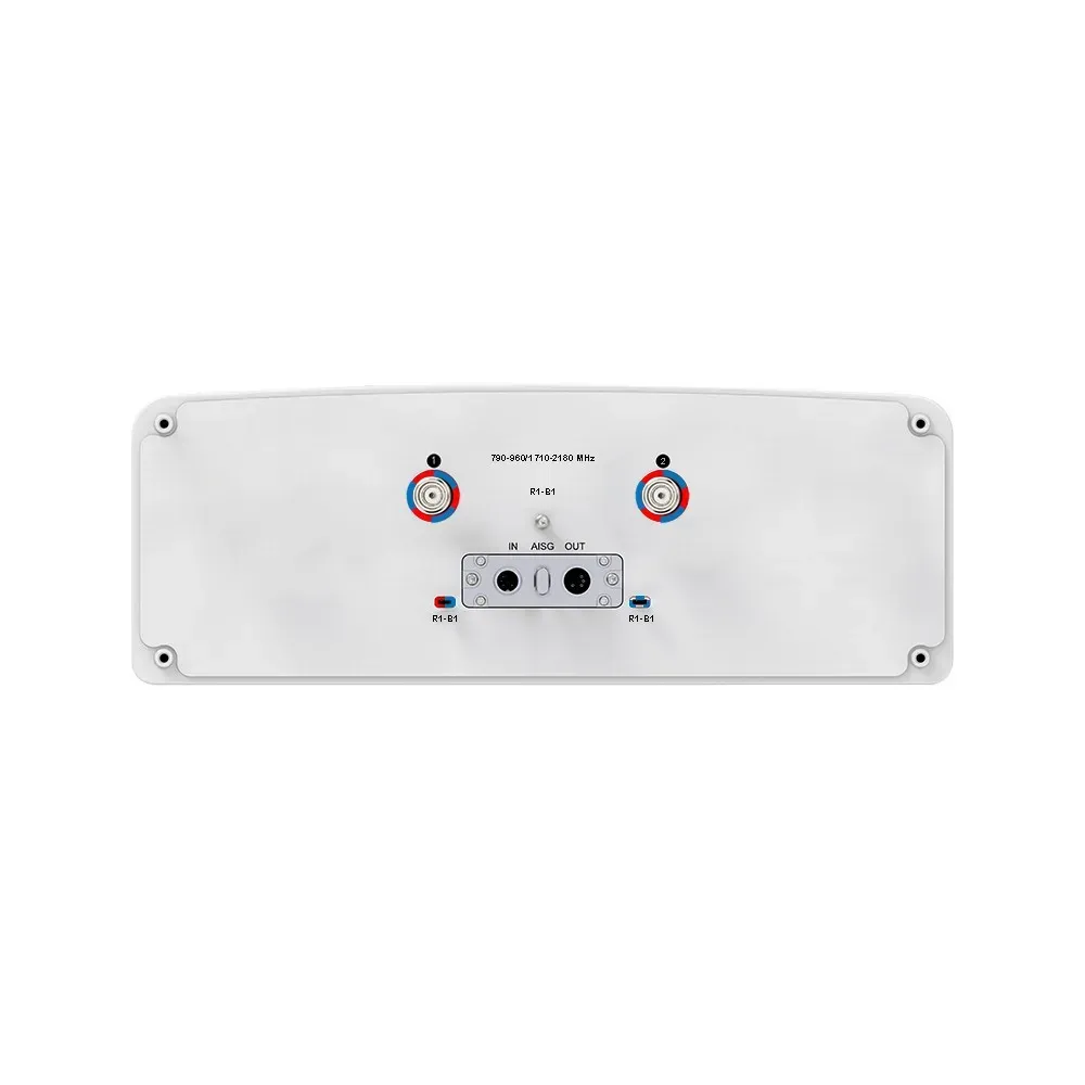
Connectors

(other connectors by request)

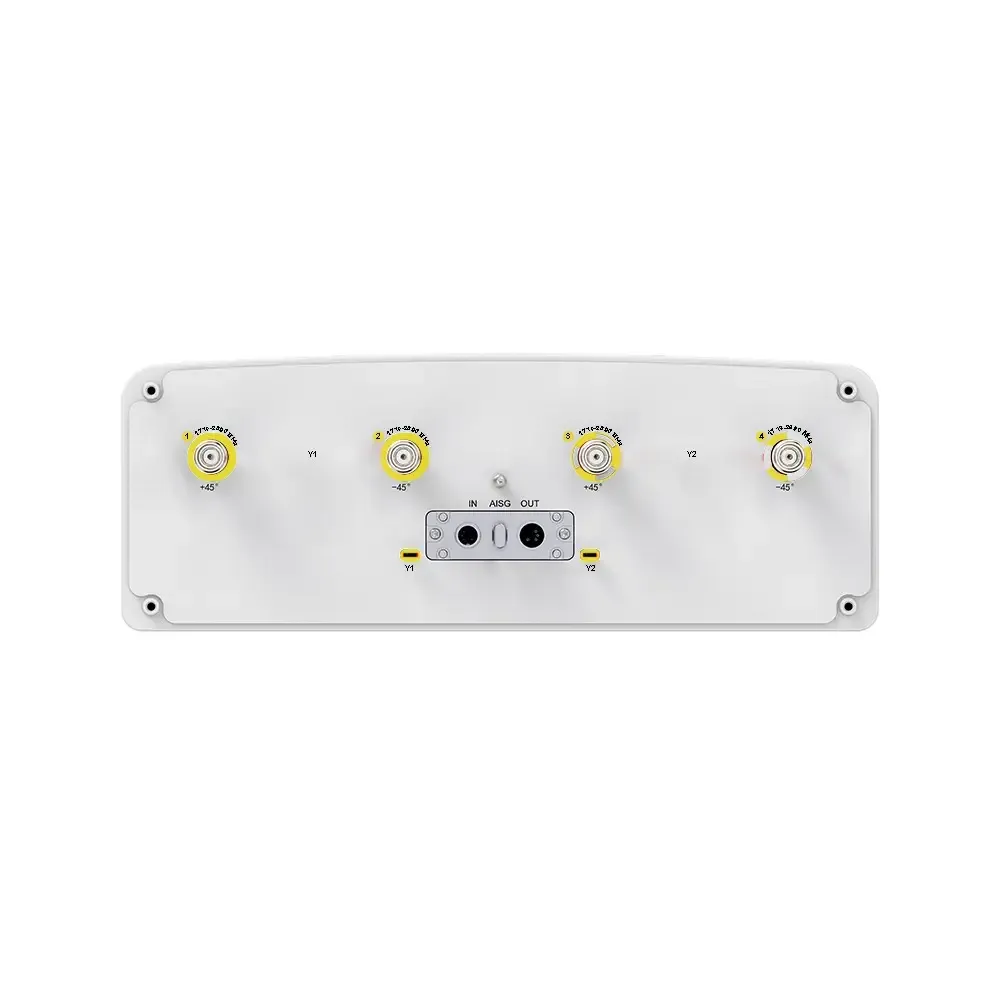
(2x) 4.3/10

Female

(2x) 4.3/10

Female

(2x) 4.3/10

Female

(2x) 4.3/10

Female

(2x) 4.3/10

Female

(2x) 4.3/10

Female

(2x) 4.3/10

Female

(1x) MQ5 Male (4 RF + 1

Calibration) & (1x) MQ4 Male (4 RF)

(1x) MQ5 Male (4 RF + 1

Calibration) & (1x) MQ4 Male (4 RF)


Product Part Number
32P-694-3800F-16G-65H9V
Electrical & Mechanical Specification
Electrical Specifications
R1R2R3Y1 / Y3Y2/Y4
Frequency RangeMHz694-862880-960694-9601427-26901695-2690
MHz694-806790-862880-960694-806790-894880-9601427-15181695-19201920-21702300-24002490-26901695-18801850-19901920-21702300-24002500-2690
Polarization±45°±45°±45°±45°±45°
Gainat Mid TiltdBi15.816.216.616.216.6171616.917.7181816.416.717.117.417.4
Over All TiltsdBi15.2 ± 0.615.6 ± 0.616.0 ± 0.615.6 ± 0.616.0 ± 0.616.4 ± 0.615.4 ± 0.616.4 ± 0.517.2 ± 0.517.4 ± 0.617.4 ± 0.615.8 ± 0.616.2 ± 0.516.6 ± 0.516.8 ± 0.616.8 ± 0.6
Horizontal Beamwidthdegree68 ± 6.564 ± 6.561 ± 6.568 ± 6.564 ± 6.561 ± 6.573 ± 6.570 ± 5.566 ± 6.065 ± 8.063 ± 9.068 ± 6.567 ± 6.564 ± 8.165 ± 6.563 ± 8.5
Vertical Beamwidthdegree8.8 ± 0.87.8 ± 0.67.2 ± 0.78.8 ± 0.87.8 ± 0.67.2 ± 0.78.1 ± 0.66.4 ± 0.85.9 ± 0.65.2 ± 0.54.8 ± 0.66.8 ± 0.66.4 ± 0.56.0 ± 0.55.4 ± 0.44.8 ± 0.6
Electrical Downtilt, Continuously Adjustabledegree2-122-122-122-122-12
Tilt Accuracydegree< 1< 1< 1< 1< 1< 1< 1< 1< 1< 1< 1< 1< 1< 1< 1< 1
Upper Side Lobe SuppressionFirst Upper LobedB> 15> 15> 15> 15> 15> 15> 15> 15> 15> 15> 15> 15> 15> 15> 15> 15
Peak to 20°dB> 14> 14> 14> 14> 14> 14> 14> 14> 14> 14> 14> 14> 14> 14> 14> 14
Front-To-Back Ratio ±30°dB> 23> 24> 25> 23> 24> 25> 22> 24> 25> 25> 24> 22> 22> 23> 24> 22
Cross PolarAt BoresightdB> 17> 17> 18> 17> 17> 18> 16> 16> 16> 16> 16> 16> 16> 16> 17> 17
DiscriminationOver SectordB> 9> 7> 6> 9.0> 7.0> 6.0> 6> 6> 5> 3> 2> 7.0> 6.0> 6.0> 4.0> 3.0
IsolationCross-PolardB> 26> 26> 26> 25> 25> 26
Port-To-PortdB> 25> 25> 25> 25> 25> 25
ImpedanceOhm5050505050
VSWR< 1.5< 1.5< 1.5< 1.5< 1.5
Return LossdB> 14> 14> 14> 14> 14
PIM3 (2×43 dBm Carrier)dBc< -150< -150< -150< -150< -150
Lightning ProtectionDC Ground
Maximum Average Input Power per Port, at 50° C Ambient TemperatureWatts200200250200200
Y5P1
Frequency RangeMHz2300-2690MHz3300-3800
MHz2300-24002490-2690MHz3300-36003600-3800
Polarization±45°±45°
Electrical Downtilt, Continuously Adjustabledegree2-12degree2-12
Beamforming Electrical PropertiesSingle Column BeamGaindBi15.6 ± 116.1 ± 1GaindBi15.5 ± 115.7 ± 1
Horizontal Beamwidthdegree85 ± 1080 ± 10Horizontal Beamwidthdegree80 ± 1070 ± 10
Vertical Beamwidthdegree5.4 ± 0.55.0 ± 0.5Vertical Beamwidth (3 dB)degree5.8 ± 0.65.5 ± 0.6
Cross-Polar Discrimination atdB≥ 16≥ 16Cross-Polar Discrimination (0°)dB≥ 15≥ 15
BoresightFirst Upper Side Lobe SuppressiondB≥ 15≥ 15
First Upper Side Lobe SuppressiondB≥ 15≥ 15Front-To-Back RatiodB≥ 25≥ 25
Front-To-Back Ratio Co-Pol, ±30°dB≥ 28≥ 28GaindB17.0 ± 0.617.2 ± 0.6
65°GaindB16. ± 117.1 ± 1Horizontal Beamwidthdegree6565
Broadcast BeamHorizontal Beamwidthdegree6565Vertical Beamwidth (3 dB)degree5.8 ± 0.65.5 ± 0.6
Vertical Beamwidthdegree5.4 ± 0.55.0 ± 0.5Cross-Polar Discrimination (0°)dB≥ 15≥ 15
Cross-Polar Discrimination atdB≥ 16≥ 16First Upper Side Lobe SuppressiondB≥ 15≥ 15
BoresightFront-To-Back RatiodB≥ 27≥ 27
First Upper Side Lobe SuppressiondB≥ 15≥ 15Service Beam0° Direct Beam GaindBi21 ± 0.521.2 ± 0.5
Front-To-Back RatiodB≥ 28≥ 280° Direct Beam Horizontal 3 dB Beamwidthdegree< 25< 25
Service Beam (0°)Direct Beam GaindB21.1 ± 121.1 ± 1±30° Direction Beam GaindBi1818.2
±30° Direct Beam GaindB19.5 ± 119.5 ± 1±30° Direction Beam Horizontal 3 dBdegree< 30< 30
Direct Beam Horizontal Beamwidthdegree23 ± 322 ± 3Beamwidth
Direct Beam Cross-Polar Ratio (0°)dB≥ 20≥ 200° Direct Beam Cross-Polar RatiodB≥ 18≥ 18
Direct Beam Azimuth Side Lobe SuppressiondB≥ 12≥ 120° Direct Beam Front-To-Back RatiodB≥ 30≥ 30
Direct Beam Front-To-Back RatiodB≥ 30≥ 30Calibration and Electrical ParameterCoupling Factor Between CalibrationdB-26 ± 2
Multi-beamGaindBi19.6 ± 120.1 ± 1And Each Antenna Port
Soft Split Electrical PropertiesMaximum Amplitude Tolerance From Calibration Port To Input PortsdB≤ 0.7
Horizontal Beamwidthdegree31 ± 329 ± 3Maximum Phase Tolerance From Calibration Port To Input Portsdegree≤ 9
Vertical 3 dB Beamwidthdegree5.4 ± 0.55.0 ± 0.5Ports VSWR< 1.5
First Uppper Side Lobe SuppressiondB≥ 17≥ 17Average Power CapacityWatts25
Front-To-Back RatiodB≥ 28≥ 28Co-Polar Isolation Bewtween PortsdB≥ 20
Calibration and Electrical ParameterCoupling Factor Between CalibrationdB-26 ± 2Cross-Polar Isolation Between PortsdB≥ 25
and each antenna portImpedanceOhm50
Maximum Amplitude Tolerance From Calibration Port to Input PortsdB≤ 0.9VSWR< 1.5
Maximum Phase Tolerance from calibration port to input portsdegree≤ 7Return LossdB> 14
IsolationCo-Polar Isolation bewtween PortsdB≥ 23PIM3 (2×43 dBm Carrier)dBc< -140
Cross-Polar Isolation Between PortsdB≥ 25Lightning ProtectionDC Ground
VSWR< 1.5
Return LossdB> 14
PIM3 (2×43 dBm carrier)dBc< -150
Lightning ProtectionDC Ground
Maximum Average Input Power Per RF PortW150
Integrated RET Specifications
ProtocolsCompliant to AISG v2.0 and 3GPP
Supply Voltage Range10-30 V DC; Compliant to AISG2.0 and 3GPP TS25.461 V6.0.0
PowerStandby< 2 W
ConsumptionIn Motion< 10 W
Connectors2 x 8 Pin Circle Connector According to IEC 60130-9 and AISG Daisy Chain In: Male; Daisy Chain Out: Female
Pin3: RS485B; Pin5: RS485A; Pin6: 10-30 V; Pin7: DC Return
Female Connector: 8 PINs; Male Connector: 4 PINs
Hardware InterfacesRS485 and Power
Adjustment Time≤ 90 sec (typical, depending on antenna type)
Adjustment Cycles> 20,000
Torque Maximum≥ 160 mN·m (@ 30RPM)
Lightning Protection RatingIEC 61000-4-5 Current Pulse Profile
Line to Ground: 8/20 µs @ 8 kA ≥ ±5 Repititions Line to Line: 8/20 µs @ 3 kA ≥ ±5 Repititions
Remote ControlCan manage from OMC, BTS/Node B
Daisy Chaining MethodReady for daisy-chaining
Safety StandardCompliant to EN 60950/UL 60950/RoHS, CE
Housing Material / ColorAluminum / Grey
Operating Temperature-40° to +70° C (-40° to +158° F)
Storage Temperature-55° to +75° C (-67° to +167° F)
HumidityUp to 95%
IP RatingIP65
Weight≤ 500 g
Mechanical Specifications
Connector Type(18X) 4.3/10 Female & (1x)MQ5 Male+ (1x) MQ4 Male
Connector PositionBottom
Electrical Tilt ControlIntegrated RET
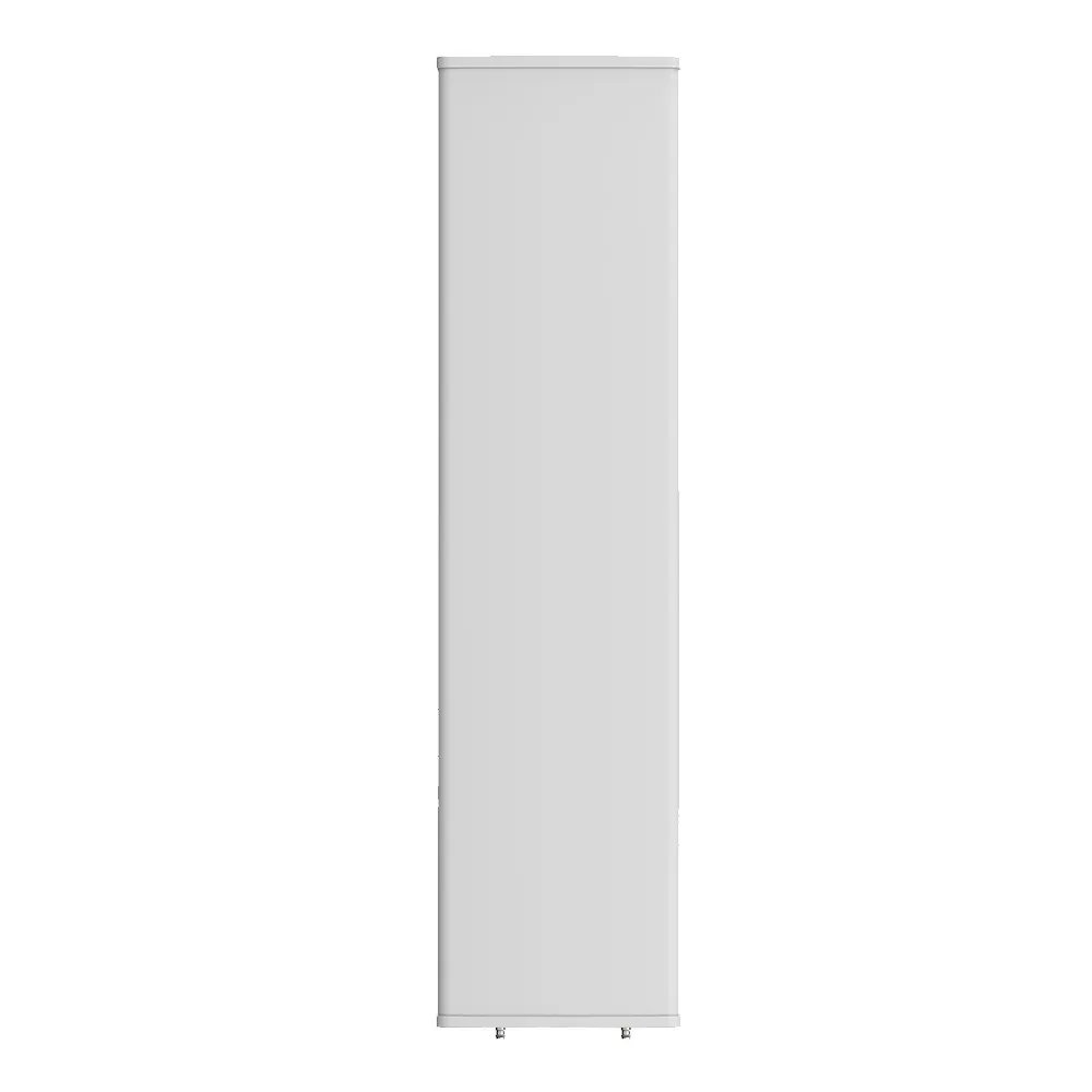
Radome MaterialFiberglass
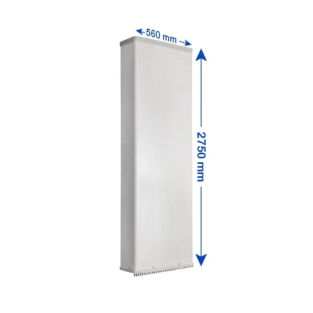
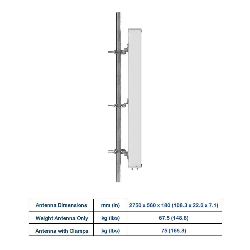
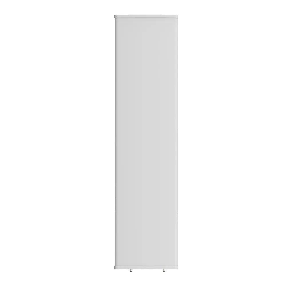
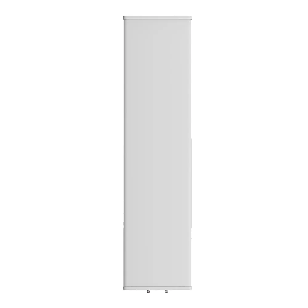
Antenna Dimensions (H x W x D)mm (in)2750 x 497 x 197 (108.3 x 19.6 x 7.8)
Antenna WeightAntenna Onlykg (lbs)64.5 (142.2)
with Clampskg (lbs)72 (158.7)
Maximum Wind Speedkm/h (mph)200 (124.3)
Wind Load at 150 km/hFrontalN (lbf)1265 (284.4)
RearN (lbf)1410 (317.0)
LateralN (lbf)620 (139.4)
Operating Temperature°C (°F)-40 to +60 (-40 to +140)
Request a Quote
Other Inquiries

Please send purchase request at sales@mtsrl.in