Product code: 9P-2300-2690F-16G-90H6V
9-Port, TDD Panel Antenna 90° HBW, 2300-2690 MHz, 16 dBi, 2-12°T, 1.497 m
9-Port Antenna | Y1 |
Frequency Range (MHz) | 2300-2690 |
HBW | 90° |
Gain | 16 dBi |
Tilt | 2-12° |
Connectors
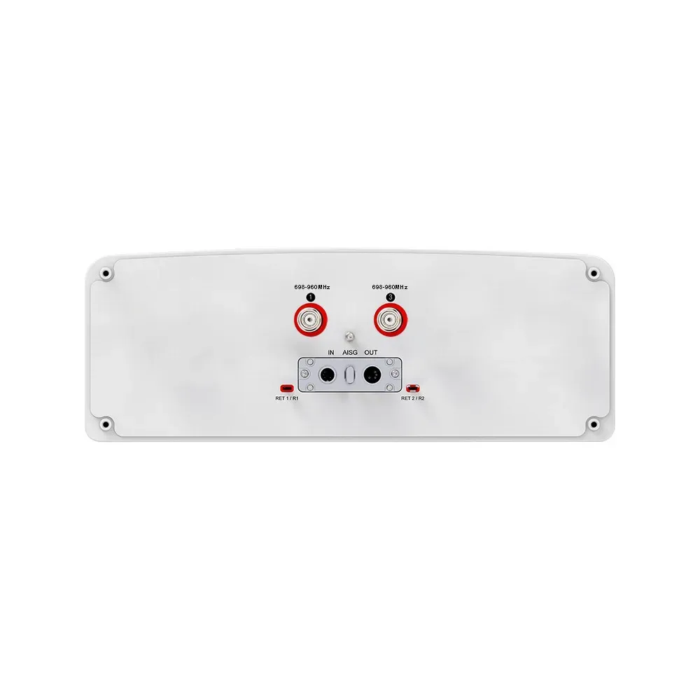
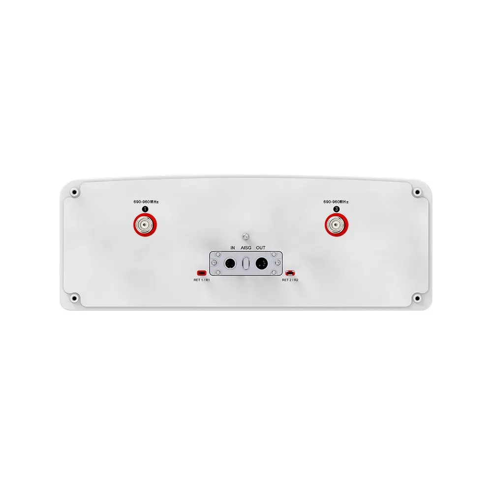
(other connectors by request) |
(8x) 4.3/10 Female &
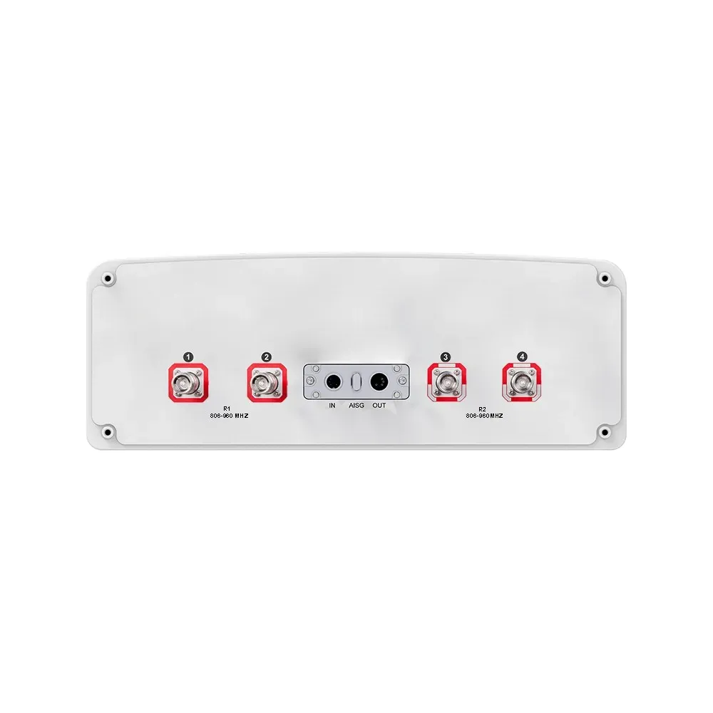
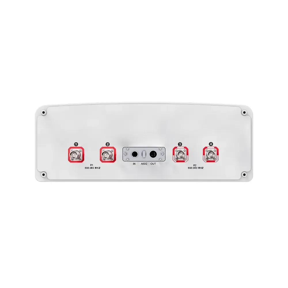
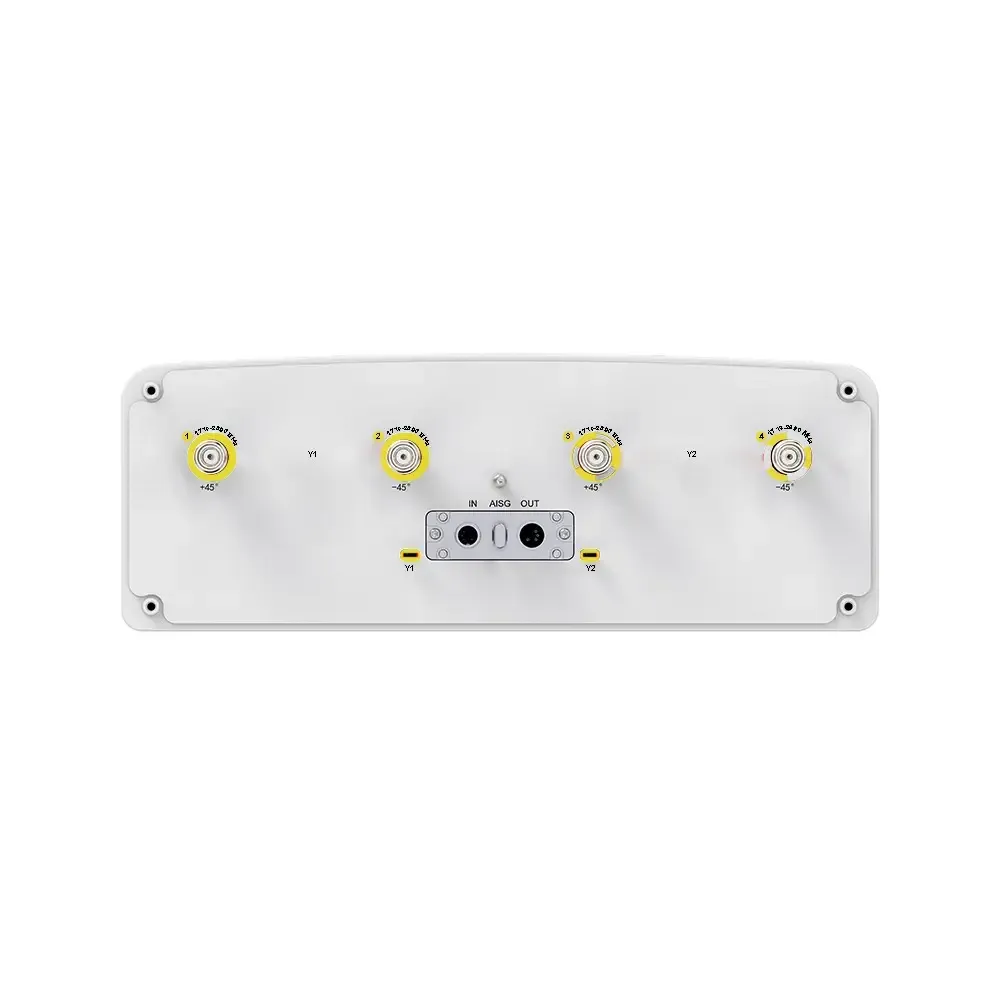
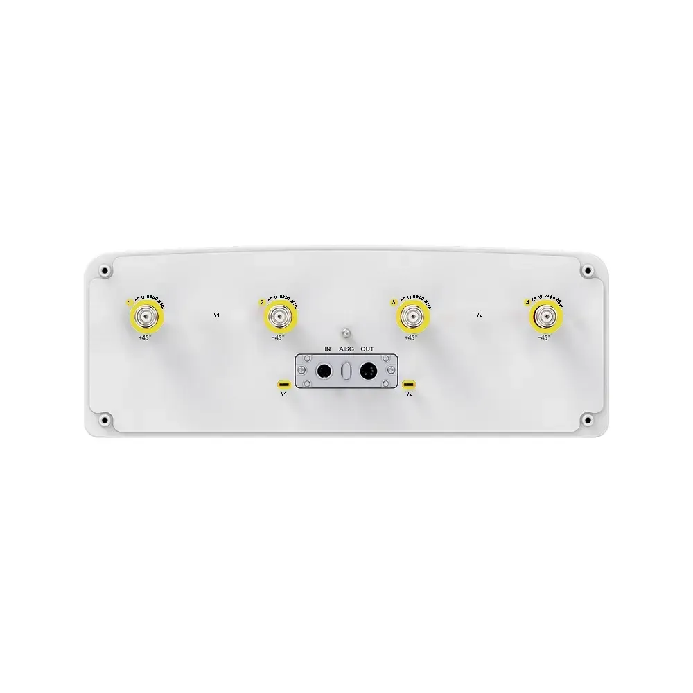
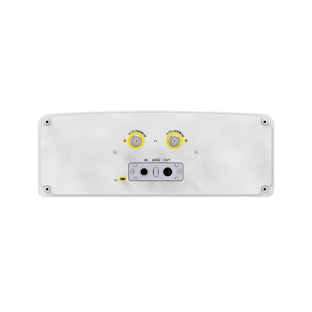
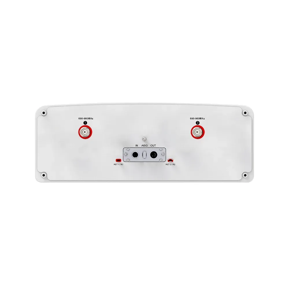
(1x) 4.3/10 Female Calibration Port |
Product Part Number
9P-2300-2690F-16G-90H6V
Electrical & Mechanical Specification
Electrical Specifications | ||||||
---|---|---|---|---|---|---|
Y1 | ||||||
MHz | 2300-2690 | |||||
Frequency Range | MHz | 2300-2400 | 2490-2690 | |||
Polarization | — | ±45° | ||||
Electrical Downtilt, Continuously Adjustable | degree | 2-Dec | ||||
Lightning Protection | — | DC Ground | ||||
Gain | dBi | 16 ± 1 | 17 ± 1 | |||
Horizontal Beamwidth | degree | 85 ± 15 | 75 ± 15 | |||
Single Column Beam | Vertical Beamwidth (3 Db) | degree | 6.0 ± 0.6 | 5.5 ± 0.6 | ||
Cross-Polar Discrimination (0°) | dB | ≥ 16 | ≥ 16 | |||
First Upper Side Lobe Suppression | dB | ≥ 16 | ≥ 16 | |||
Front-To-Back Ratio, ±30° | dB | ≥ 25 | ≥ 25 | |||
Gain | dBi | 17.5 | 18 | |||
Horizontal Beamwidth | degree | 65 | 65 | |||
65° | Vertical Beamwidth | degree | 6.0 ± 0.6 | 5.5 ± 0.6 | ||
Broadcast Beam | Cross Polar Discrimination At Boresight | dB | ≥ 16 | ≥ 16 | ||
Front-To-Back Ratio | dB | ≥ 25 | ≥ 25 | |||
First Upper Sidelobe Suppression | dB | ≥ 16 | ≥ 16 | |||
0° Direct Beam Gain | dBi | 21 | 21.5 | |||
0° Direct Beam Horizontal Beamwidth (3 dB) | degree | 26 | 24 | |||
0° Direct Beam Cross-Polar Ratio (0°) | dBi | ≥ 17 | ≥ 17 | |||
0° Direct Beam Horizontal Side Lobe Level | dB | 12 | 12 | |||
Service | 0° Direct Beam Front-To-Back Ratio | dB | ≥ 30 | ≥ 30 | ||
Beam | ±30° Direct Beam Gain | degree | 19.5 | 20 | ||
±30° Direct Beam Horizontal Beamwidth (3 dB) | degree | 29 | 26 | |||
±30° Direct Beam Gain Front-To-Back Ratio | dB | ≥ 25 | ≥ 25 | |||
Soft Split Electrical Properties | Gain | dBi | 20 | 20.5 | ||
(Multi-Beam) | Horizontal Beamwidth | degree | 30 | 28 | ||
Front-To-Back Ratio | dB | ≥ 25 | ≥ 25 | |||
Coupling Factor Between Calibration Port | dB | -26 ± 2 | ||||
And Each Antenna Port | ||||||
Max. Amplitude Tolerance From | dB | ≤ 1.0 | ||||
Calibration Port To Input Ports | ||||||
Max. Phase Tolerance From Calibration Port | degree | ≤ 9 | ||||
Calibration & Electrical Parameters | To Input Ports | |||||
Ports VSWR | — | < 1.5 | ||||
Return Loss | dB | > 14 | ||||
Max. Average Input Power Per RF Port | W | 50 | ||||
Co-Polarization Isolation Between Ports | dB | ≥ 25 | ||||
Cross-Polarization Isolation Between Ports | dB | ≥ 25 | ||||
Integrated RET Specifications | ||||||
Protocols | Compliant to AISG v2.0 and 3GPP | |||||
Supply Voltage Range | 10-30 V DC; Compliant to AISG2.0 and 3GPP TS25.461 V6.0.0 | |||||
Power | Standby | < 2 W | ||||
Consumption | In Motion | < 10 W | ||||
Connectors | 2 x 8 Pin Circle Connector | |||||
Pin3: RS485B; Pin5: RS485A; Pin6: 10-30 V; Pin7: DC Return | ||||||
Female Connector: 8 PINs; Male Connector: 4 PINs | ||||||
Lightning Protection Rating | IEC 61000-4-5 Current Pulse Profile | |||||
Line to Ground: 8/20 µs @ 8 kA ≥ ±5 | ||||||
Safety Standard | Compliant to EN 60950/UL 60950/RoHS, CE | |||||
Mechanical Specifications | ||||||
Connector Type | — | (8x) 4.3/10 Female and (1x) 4.3/10 Female | ||||
Connector Position | — | Bottom | ||||
Electrical Tilt Control | — | Integrated RET | ||||
Radome Material | — | UPVC | ||||
Antenna Dimensions (H x W x D) | mm (in) | 1497 x 277 x 167 (58.9 x 10.9 x 6.6) | ||||
Antenna Weight | Antenna Only | kg (lbs) | 16 (35.3) | |||
With Clamps | kg (lbs) | 20 (44.1) | ||||
Maximum Wind Speed | km/h (mph) | 200 (124.3) | ||||
Wind Load | Frontal | N (lbf) | 385 (86.6) | |||
At 150 | Rear | N (lbf) | 430 (96.7) | |||
Km/H | Lateral | N (lbf) | 285 (64.1) | |||
Operating Temperature | °C (°F) | -40 to +60 (-40 to 140) |
Request a Quote
Other Inquiries
Please send purchase request at sales@mtsrl.in